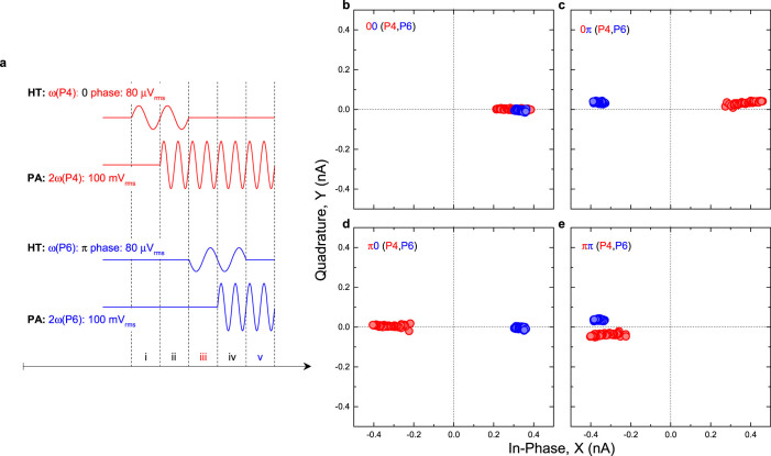
Figure 3. An electromechanical byte memory.
(a), The pulse sequence used to execute a 2-bit byte in the electromechanical parametric resonator array where the steps to write the string 0π are shown. Note that the parametric actuation amplitudes of modes P4 and P6 need to be modified when compared to the instability tongues in Figs. 2e and 2f to enable both modes to be activated in unison. (b–e), The response of modes P4 and P6, when subjected to the above sequence with the measured outputs projected in phase space confirm the successful execution of a 2-bit byte. The responses of modes P4 and P6 are smeared out by different amounts due to their parametric actuation frequencies being increased across their respective instability tongues (along the schematic black arrows in Figs. 2e and 2f) enabling the electromechanical byte memory to be more easily readout.

