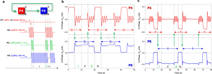
Figure 5. The electromechanical shift register.

(a), The block diagram summarising the corresponding pulse sequence used to implement a shift register in the electromechanical parametric resonator array where logical 0 or π is first written via the harmonic trigger and stored in mode P4 via its parametric resonance. This information is then shifted via the parametric coupling pump and stored in mode P6 (steps i and ii). The same information is then shifted back to P4 for storage (steps iii and iv) following which it is repeatedly cycled between the 2 modes where this process preserves phase information and the storage time in steps ii and iv can be varied as desired. (b) (c), Implementation of the pulse sequence described in Fig. 5a where logical 0 (π) is first prepared by the harmonic trigger resulting in positive (negative) in-phase components for the parametric modes P4 and P6 where this information can be stored for (un)equal durations in steps ii and iv and be repeatedly cycled between them. Note also that when the parametric coupling pump is activated in steps i and iii, it causes the parametric resonance of mode P4 to fluctuate during the information transfer.
