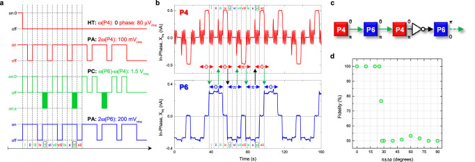
Figure 6. The electromechanical CNOT gate.

(a) and (c), The pulse sequence used to implement an inverter logic gate and the corresponding block diagram respectively. The phase information being shifted between parametric modes P4 and P6 is expected to undergo inversion by introducing a π phase shift in the parametric coupling pump as depicted in steps v and steps xi. (b), The experimental implementation of the pulse sequence described in Fig. 6a clearly confirms that the 0 (π) logical is inverted to π (0) when it is shifted from mode P4 (P6) to P6 (P4) in step v (xi) only by introducing the controlled π phase shift into the parametric coupling pump. Note also that the parametric resonance of mode P4 fluctuates when the parametric coupling pump is activated. (d), The fidelity of the invertor shift between elements of the electromechanical parametric resonator array when subjected to the pulse sequence described in Fig. 6a as a function of the phase difference around the parametric coupling pump with ϕ = π. The invertor logic gate can be executed with 100% fidelity when the parametric coupling pump operates with phase differences close to its node namely at ϕ = π.
