

Abstract
In order to exploit the use of favorable electrostatic interactions between aromatic units in directing the assembly of donor-acceptor (D-A) dyads, the present work examines the ability of conjugated aromatic D-A dyads with symmetric side chains to exhibit solid-state polymorphism as a function of time during the solid formation process. Four such dyads were synthesized and their packing in the solid-state from either slower (10-20 days) or faster (1-2 days) evaporation from solvent was investigated using single crystal X-ray analysis and powder X-ray diffraction. Two of the dyads exhibited tail-to-tail (A-A) packing upon slower evaporation from solvent and head-to-tail (D-A) packing upon faster evaporation from solvent. A combination of single crystal analysis and XRD patterns were used to create models wherein a packing model for the other two dyads is proposed. Our findings suggest that while side chain interactions in asymmetric aromatic dyads can play an important role in enforcing segregated D-A dyad assembly, slowly evaporating symmetrically substituted aromatic dyads allows for favorable electrostatic interactions between the aromatic moieties to facilitate the organization of the dyads in the solid-state.
Introduction
The efficiency of organic material devices, such as organic light-emitting diodes (OLEDs) and organic field-effect transistors (OFETs), is intrinsically tied to the morphology of an electron donor (D) and electron acceptor (A) in the active layer of the device.1-3 When blends of D and A are cast in the active layer, non-covalent interactions, such as van der Waals interactions, charge transfer and other electrostatic interactions, play a role in defining their supramolecular order.2 While bicontinuous D and A regions are crucial for device efficiency, D-A charge transfer complexes often occur leading to poor charge carrier mobility. Another morphologically-controllable alternative to D and A blends are covalently linked D-A dyads and represent one of the simpler “bottom-up” methods for obtaining long-range order in the active layer of organic material devices.1,4,5 A myriad of D-A dyads have been synthesized and studied. While Müllen and co-workers primarily focus on dyads composed of hexa-peri-hexabenzocoronene (HBC) linked to perylenetetracarboxy-diimide (PDI) and –monoimide (PMI,2,4,6-8 Aidi and co-workers have developed amphiphilic oligothiophene-C609 and HBC-C60 dyads.10 Venkataraman and co-workers have studied amphiphilic naphthalimide (NI)–naphthyl11 and naphthalene diimide (NDI)-quaterthiophene (QT) D-A dyads12 while Würthner et al. studied the effects of hydrogen bonding on the assembly of oligo(p-phenylene vinylenes) (OPVs) and perylene bisimides (PERYs) into p-n heterojunctions.13
Several strategies have been used to direct segregated stacking in bulk heterojunction structures. In 2007, Benanti, Saejueng and Venkataraman designed D-A dyads that took advantage of the immiscibility of hydrocarbon and fluorocarbon side chains appended to aromatic moieties to induce segregated D-A domains composed of aromatic acceptor-acceptor stacking between the NI units.11 More recent work by Aida and co-workers utilized a similar immiscible side chain scaffold to promote the D-A segregation of D-A dyads into a lamellar stacking arrangement9 and coaxial nanotubes.10 Taking a simpler route to achieve segregated stacking, Samorì et al. used a technique called solvent induced precipitation to form fibers composed of D-A dyads.7
Non-covalent interactions play decisive roles in defining highly ordered architectures such as foldamers,14 catenanes,15,16 rotaxanes,17,18 and materials with interesting electronic properties.4,6,9 In most of these systems, a careful interplay of solvaphobic interactions coupled with complementary electrostatic interactions between aromatics drive the system assembly. In the 1990s, Hunter and Sanders laid the foundation for a theoretical understanding of interactions between aromatic units by suggesting that interactions between the overall quadrupole moments of aromatic moieties direct the stacking geometry between adjacent molecules.19 Typical geometries include the herringbone geometry favored by two electron-rich aromatics, the off-set parallel stacking geometry favored by two electron-deficient aromatics and the face-centered stacking geometry favored by one relatively electron-rich aromatic interacting with a relatively electron-deficient aromatic.
Recent computational work by Wheeler and Houk20 and more recently by Wheeler21 has refined our understanding of aromatic stacking by theorizing that local, direct through-space interactions between polarized moieties on the periphery of the aromatic units can better explain the observed stacking geometries. This model has been called the “direct, interaction model.” Early experimental work by Rashkin and Waters22 as well as computational work by Sherrill and co-workers,23-25 Snyder et al.,26 Lee et al.,27 Wheeler et al.,28 and Grimme29 have all highlighted the role of direct substituent-substituent interactions between stacked aromatic units as a predictor of aromatic stacking.
Using the aforementioned notions of complementary electrostatic interactions, several groups have designed molecular systems capable of conformationally switching between an alternating relatively electron-rich and relatively electron-deficient face-centered stacked assembly (D-A stacking) to non-alternating parallel off-set stacked assemblies of just the relatively electron deficient aromatics (A-A stacking), and vice versa. For example, Matile et al. successfully demonstrated switching between a “closed” relatively electron-deficient naphthalene diimide (NDI) off-set parallel displaced self-assembled ion channel to an “open” ion channel by adding the relatively electron-rich dialkoxynaphthalene (DAN) monomer into the solution that then intercalated between NDI units in a face-centered, stacked geometry ultimately straightening out (“opening”) the ion channel.30 In 2010, Ghosh et al. used the strength of hydrogen-bonding over aromatic interactions to force the segregation of an initially face-centered stacked NDI and DAN alternating assembly into segregated NDI and DAN monomer assemblies in a gel state.31 Research in our group has observed the irreversible conformational switching of a pleated, NDI-DAN face-centered stacked foldamer to a NDI-NDI fibril aggregate14 as well as the sterically-induced self-sorting of DAN and NDI monomers in a mesophase to separated NDI-NDI and DAN-DAN aromatic assemblies upon cooling to the crystalline phase.32
Polymorphism, or the ability of one molecule to form two or more distinct crystal structures, is a well-documented phenomenon and is influenced by numerous parameters such as additives and solvent.33 Conformational twisting34 and cis-to-trans conformational switching35-37 are examples of solvent induced polymorphism observed in small molecules. Work by Myerson et al. explored the effect of solvent evaporation rate on the polymorphism of glycine crystals and found that a slower evaporation time lead to the more stable polymorph of glycine.38 To our knowledge, however, the solid-state polymorphism of conjugated aromatic D-A dyads using slower and faster evaporation rates has not yet been reported.
For the first time, the present work examines the ability of conjugated aromatic D-A dyads with symmetric side chains to exhibit solid-state polymorphism as a function of time during the solid formation process. More specifically, while single crystal X-ray and XRD analyses revealed head-to-tail D-A stacking for all four of the D-A dyads derived from fast evaporation, relatively slow evaporation lead to a tail-to-tail A-A packing geometry in two cases.
Experimental Section
Dyad Synthesis
The synthesis, experimental details and characterization of dyads 1 – 4 can be found in the supplementary information.
X-ray Crystallography
X-ray crystallography was performed on a Nonius Kappa CCD diffractometer using a Bruker AXS Apex II detector and a graphite monochromator with MoKα radiation (λ = 0.71075Å). Specific instrumentation details for each obtained single crystal are located in the supplemental section.
Powder X-Ray Diffraction
X-ray powder diffraction (XRD) patterns were obtained with a Scintag X1 theta–theta diffractometer equipped with a Cu X-ray tube and a solid-state X-ray detector set to count Cu Kα radiation. Samples were prepared by placing the solid dyads onto a zero background quartz plate sample holder.
Results and Discussion
Synthesis and electrostatic potential maps
A series of four dyads bearing shorter and longer alkyl chains were synthesized via Sonogashira couplings between aromatic naphthalimide (NI) and monoalkoxynaphthalene (MAN) units (Figure 1) in order to test the influence of chain length and orientation on solid state packing. In particular, both 2,6- and 1,4-position substituted MAN units were synthesized containing either one or eight carbon chains.
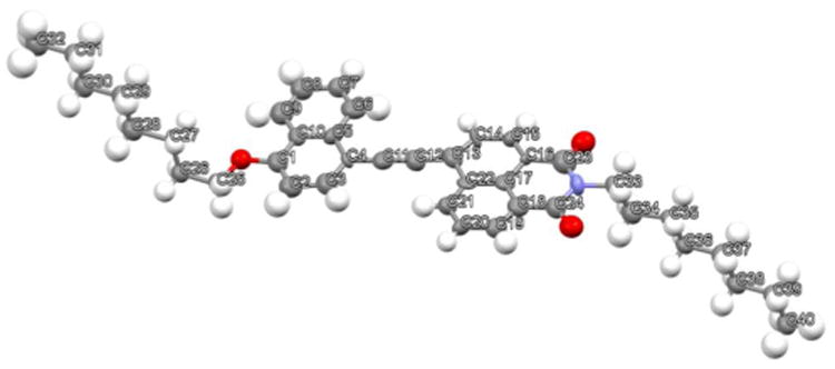
Figure 1.

Structures and electrostatic potential maps of dyads 1 - 4 generated in Spartan using the DFT B3LYP G-31* method.
Electrostatic potential maps of dyads 1 - 4 are shown in Figure 1. The most striking feature of all the dyads is the strong polarization of the NI carbonyl bonds, rendering the carbonyl oxygen atoms electron-rich while leaving the carbonyl carbon atoms relatively electron-deficient. One might anticipate intuitively that the NI portion would be significantly more electron-deficient relative to the MAN portion than what is seen in Figure 1. Although there is a difference, the overall electronic similarities seen near the center of each aromatic unit are attributable, at least in part, to delocalization of the MAN electron-density onto the NI unit through the alkyne linker.39,40
In order to determine the dyad packing in the solid state, various conditions were used to grow crystals of the dyads. Powder XRD patterns of those crystals were then obtained and compared to XRD patterns obtained from either slower or faster evaporation from toluene. We could then determine the packing structure of the dyads, even for those without a crystal structure, based on comparing the two sets of XRD data.
Single crystal analysis
Crystals suitable for structural analysis were grown from either slower (20 days for 1, 10 days for 4) or faster (1 day for 1) evaporation from solvent systems that were empirically found to be capable of growing high quality crystals. “Fast” crystals of dyad 1 were grown from chloroform while “slow” crystals of dyad 1 and 4 were grown from 1:1:1 Toluene:MeOH:Ethyl Acetate and 1:1:1 DCM:MeOH:Acetone, respectively. Typically, ∼5.0 mg of dyad were placed in a scintillation vial and dissolved in 10 mL of solvent. For slower evaporations the vials were partially closed while faster evaporations were performed without a cap. Numerous attempts at growing high quality crystals of dyads 2 and 3 gave at best hair-like solids that did not refract.
Dyad 1
Dyad 1 was found to form two distinct crystals as a function of crystal growth time and solvent system: a head-to-tail (MAN-NI aromatic interaction) crystal after faster evaporation from chloroform and a head-to-head (NI-NI aromatic interaction) crystal after slower evaporation from 1:1:1 Toluene:MeOH:Ethyl Acetate. The head-to-tail crystal resulting from fast evaporation is nearly planar and exhibits stacking in which the MAN portion of one dyad stacks in a face-centered fashion with the NI portion of another (Figure 2). The NI portion of the aforementioned dyad is situated directly above the NI portion of another dyad (Figure 3a). While the NI-MAN centroid-centroid distance is 3.73 Å, the NI-NI centroid-centroid distance is 4.0 Å. The plane-to-plane distance between the stacked dyad layers is 3.33 Å. Within the same column, the dyads are ∼55° offset along the dyad short-axis. The bond lengths between C14≡C15 (1.198 Å), C5-C14 (1.431 Å) and C15-C16 (1.428 Å) are relatively short suggesting delocalization between the NI and MAN unit41 and are all within standard bond lengths for other NI-containing systems.42,43 The head-to-tail dyad pairs reside in rows that do not show any overlap between dyads of either row (Figure 3b). Looking down the crystallographic A-axis reveals that each row can be divided further into columns (Figure 3c). Bond lengths within the NI dicarboximide ring are typical and are in good agreement with bond lengths in other NI-containing systems.42,43
Figure 2.

Structure of quickly evaporated dyad 1 showing the atom-numbering scheme with ellipsoids scaled at the 50% probability level. A molecule of chloroform has been removed from the asymmetric unit for clarity.
Figure 3.

Crystal structure of quickly evaporated dyad 1 showing (a) Head-to-tail, MAN-NI packing occurs between dyads directly above each other while NI-NI interactions occurs between adjacent pairs; (b) side view of crystal packing showing rows of non-interacting dyads; and (c) view down crystallographic A-axis shows details of crystal packing.
When evaporated more slowly from 1:1:1 Toluene:MeOH:Ethyl Acetate, dyad 1 displayed a nearly planar relationship between the NI and MAN units with the dyads packing in a tail-to-tail fashion (Figure 4).
Figure 4.

Asymmetric unit of slowly evaporated dyad 1 showing the atom-numbering scheme with ellipsoids scaled at the 50% probability level. A molecule of toluene was removed from the unit for clarity.
While the plane-to-plane distance between dyads is slightly larger (3.36 Å compared to 3.33 Å when quickly evaporated), the dyads are ∼20° off-set from each other along the dyad short-axis in the same column (Figure 5a). The NI-NI centroid-centroid distance for the pair of dyads in the asymmetric unit is 3.72 Å while the NI-NI centroid-centroid distance between asymmetric units is 3.76 Å. The bond lengths between both molecules in the asymmetric cell are C14≡C15 (1.191 Å) and C41≡C40 (1.200 Å), C5-C14 (1.423 Å) and C31-C40 (1.420 Å), and C15-C16 (1.444 Å) and C41-C42 (1.425 Å) are all relatively short suggesting delocalization between the NI and MAN unit.41 Again, all bond lengths within the NI unit are consistent with those previously seen in NI-containing systems.42,43 Rows of non-interacting dyads are shown in Figure 5b. Interestingly, extended columns of aromatic-aromatic (NI-NI) interactions occur in the more slowly evaporated crystal (Figure 5c), unlike what was observed in the crystal obtained upon more rapid evaporation described above.
Figure 5.

Crystal structure of slowly evaporated dyad 1 showing (a) tail-to-tail, NI-NI packing occurs between two dyad molecules situated in one asymmetric unit; (c) side view of crystal packing showing rows of non-interacting dyads; and (b) NI-NI aromatic interactions among columns as viewed from crystallographic C-axis.
Dyad 4
The crystal structure of dyad 4 produced upon slower evaporation from 1:1:1 DCM:MeOH:Acetone also reveals a tail-to-tail (A-A) stacking geometry, with the NI unit being nearly coplanar with the MAN unit (Figure 6).
Figure 6.
Structure of slowly evaporated dyad 4 showing the atom-numbering scheme with ellipsoids scaled at the 30% probability level.
As shown in Figure 7a, the dyads are packed in an off-set parallel-displaced fashion with the NI portions of adjacent dyads stacking on top of each other. The plane-to-plane distance is 3.36 Å and the stacked dyads show an off-set angle of ∼45° along the dyad long-axis. The NI-NI centroid-centroid distance is 4.73 Å. Unsurprisingly, the bond lengths between C11≡C12 (1.220), C4-C11 (1.414) and C12-C13 (1.435) are all relatively short suggesting delocalization between the NI and MAN unit.41 Looking down the crystallographic C-axis, adjacent columns of stacked dyads exist in the same conformation, however, the orientation of the stacks are rotated 90° relative to every other stack (Figure 7b). Adjacent columns of stacked dyad 4 pack with octyl side chains interdigitated in a lamellar fashion (Figure 7c).
Figure 7.

Crystal structure of slowly evaporated dyad 4 showing (a) off-set parallel-displaced packing between adjacent aromatic NI units; (b) orthogonal crystal packing between rows of stacked dyads along the C-axis; and (c) interdigitated side-chains among rows reminiscent of lamellar structure along the A-axis.
Powder X-ray diffraction (XRD)
Because high quality single crystals could not be obtained for each dyad, powder XRD was performed on dyads 1 - 4 to gain insight into their molecular packing morphology. XRD patterns were collected on each dyad after having been relatively slowly (10 and 15 days for 4 and 2, respectively) and more quickly (1 day for 1 - 4) evaporated from toluene. Typically, ∼ 5.0 mg of dyad was dissolved in 10 mL of toluene. Although numerous solvents and longer (30 days) evaporation times were tested to give rise to the more slowly formed polymorphs, all attempts only resulted in the one polymorph for 2 and 3. Toluene was chosen due to its relatively high boiling point and its ability to solubilize all four dyads. Initial evaporations from DCM, and other lower boiling point solvents, occurred too quickly (<4 days) and did not allow for a longer time-scale evaporation. Most importantly, using the same solvent for each powder sample insured that any differences in structure are not the result of solvent interactions, but rather reflect the influence of evaporation time.
XRD - single crystal by various solvents
For calibration purposes, XRD of the dyad crystals used for single crystal analyses were compared to XRD patterns of the same dyads quickly or slowly evaporated from toluene (see Figure 8). For the slower evaporated dyad 4 and both the faster and slower evaporated dyad 1, the XRD patterns are the same between the single crystals that were grown from different solvents and from the powders obtained via evaporation strictly from toluene. Therefore, although different solvents were used to obtain the crystals for single crystal analysis, it is assumed that the obtained crystals had the same molecular morphology as the powders obtained via evaporation from toluene. The XRD data has thus established an important structural link between materials obtained by either faster or slower evaporation that is independent of solvent composition, at least in these specific cases.
Figure 8.

Comparisons of XRD patterns between dyad single crystals grown from various solvents (top, blue lines) and powders of dyads evaporated from toluene (bottom, red lines). Inset graph shows a magnified XRD pattern. (a) Dyad 1 faster evaporation; (b) Dyad 1 slower evaporation; (c) Dyad 4 slower evaporation.
XRD – powders by toluene evaporation
Powder XRD patterns for dyads 1 - 4 after slower and faster evaporation from toluene are shown in Figure 9. For dyad 1, the slower and faster evaporated powders show patterns that can be easily distinguished from one another. Dyad 4 also shows two distinct patterns between the evaporated powders obtained from relatively slow and fast evaporation conditions. Interestingly, dyads 2 and 3 show very similar diffraction patterns between their respective powders produced upon slower and faster evaporation.
Figure 9.

Powder XRD patterns obtained from toluene for (a) Dyad 1; (b) Dyad 2; (c) Dyad 3; and (d) Dyad 4 are shown with peaks labeled and their corresponding d-spacing values listed in the accompanying table. Relatively slower evaporated dyads are shown on the bottom (in orange) while relatively faster evaporated dyads are shown on top (in blue). Inset graphs show magnified XRD patterns.
Dyad 1
The XRD d-spacing values for more quickly evaporated dyad 1 nicely match up with patterns found in the associated quickly evaporated crystal structures (see Supporting Figure S1). For the more quickly evaporated crystal structure, d-spacing values of 3.4 and 4.0 Å (similar to 3.7 Å found by XRD) represent the interplanar distances between the dyads and centroid-centroid distances between NI units, respectively.11,44-49 Single crystal distances of 8.4 and 8.6 Å were also found to be in good agreement with XRD d-spacing values (8.3 and 8.7 Å, respectively).
The crystal structure of slowly evaporated dyad 1 shows spacing distances that are also in good agreement with the XRD d-spacing values (see Supporting Figure S2). While XRD d-spacings of 3.4, 7.8 and 9.5 Å exactly match patterns from the crystal structure, a d-spacing value of 6.3 Å closely resembles the 6.2 Å value from the crystal structure.
Dyad 2
Both the fast and slow evaporation of dyad 2 from toluene gave similar powder XRD patterns (Figure 9b). Proposed interdigitation of the dyad octyl chains in a lamellar-fashion corresponds to a distance (27.5 Å) that is shorter than the distance across the dyad diagonal structure (33.5 Å).50,51 The proposed packing model therefore incorporates lamellar-type packing and uses the crystal structure of dyad 1 to arrange dyad 2 in a similar head-to-tail (D-A) stacking geometry (see Figure 10a). The observed d-spacings of 9.2 and 13.8 Å were then incorporated into our proposed model to give a final molecular packing similar to that of quickly evaporated dyad 4. A d-spacing at 3.5 Å is also in good agreement with previously reported values for aromatic-aromatic stacking interactions. 11,44-49
Figure 10.

Proposed molecular packing for (a) dyad 2; (b) dyad 3; and (c) quickly evaporated dyad 4. Important XRD d-spacing values are highlighted for each model. Scale representations of the dyads are shown in the dashed boxes (blue and red represent the NI and MAN portion of the dyad, respectively) and only represent that dyad. The middle sections show the side view of packing while the right sections show the top-down packing view.
Dyad 3
Both the fast and slow evaporation of dyad 3 from toluene gave very similar powder XRD patterns suggesting that, like dyad 2, the solid produced by dyad 3 is isomorphic for both evaporation times (see Figure 9c). Note that the XRD patterns for dyad 3 are similar to the XRD patterns observed for the more quickly evaporated dyad 1 (see Figure 9a). As a result, it is proposed that in both the faster and slower evaporation solids, dyad 3 is ordered in a head-to-tail (D-A) fashion, similar to the crystal structure of more quickly evaporated dyad 1 (see Figure 10b). In the proposed model for dyad 3, a plane-to-plane distance of 3.4 Å fits the observed XRD d-spacing while a d-spacing at 7.4 Å represent the distance between the centers of the dyad rows. The d-spacing at 3.4 Å is in agreement with previously reported values for aromatic-aromatic stacking interactions. 11,44-49 Further d-spacings can be identified in Figure 10b which support the proposed model of molecular packing for dyad 3.
Dyad 4
While single crystals suitable for X-ray analysis were only obtained for dyad 4 when the sample was evaporated slowly, XRD results showed that two distinct molecular packing arrangements exist between the quickly and slowly evaporated solids as shown in Figure 9c. For the slowly evaporated structure, a d-spacing of 21.9 Å nicely fits an interdigitated lamellar packing as scene in the obtained crystal structure (see Supporting Figure S3). Further d-spacings of 3.4 and 4.2 Å (which is very similar to a d-spacing of 4.2 Å found by XRD) represent interplanar distances between the dyads and centroid-centroid distances between NI units, respectively.
For the more quickly evaporated structure, an intense diffraction peak at 2θ = 3.1° corresponds to a d-spacing of 28.3 Å suggesting that the side chains are also packing in an interdigitated lamellar50,51 as proposed in our packing model in Figure 10c. Note that given the diagonal length of dyad 4 is 31.3 Å between the terminal carbons on the alkyl chains, this packing model makes sense according to the lamellar structure that was observed in the dyad 4 slow crystal structure. In good agreement with the proposed model, d-spacings of 7.1 and 14.2 Å represent symmetric planes found within the proposed packing model. The d-spacing at 3.4 Å is in good agreement with the interplanar distance typically found between pairs of stacked NI-NI11,44,45 and NDI-NDI46-49 aromatic units.
Conclusion
Overall, our results indicate that in conjugated aromatic D-A dyads, solid-state polymorphic molecular assembly can be achieved depending on the evaporation rate of the dyad from solvent. Single-crystal X-ray crystallography combined with powder XRD revealed that two of the four dyads displayed polymorphic behavior and stacked in a tail-to-tail NI-NI (A-A) fashion when more slowly evaporated from solvent while exhibiting head-to-tail MAN-NI (D-A) stacking when more quickly evaporated from solvent. Apparently, the length of the alkyl chain appended to the dyads did not direct the molecular packing of the aromatic units, nor did the alkoxy substitution geometry (at the 2,6- or 1,4-position) of the MAN aromatic unit, although these parameters are obviously important factors in the details of the packing geometries seen. Interestingly, the two dyads (2 and 3), that displayed only one type of packing following evaporation at either rate gave XRD patterns predicted to derive from head-to-tail (D-A) stacking. Thus, while all the dyads could stack in a head-to-tail D-A fashion, only 1 and 4 could produce a solid with stacking in a tail-to-tail A-A fashion, but only when evaporated more slowly.
DFT calculations of the dyad electrostatic potentials gave some level of insight as to why the head-to-head NI-NI (A-A) packing state could be observed for the more slowly evaporated 1 and 4. It is assumed, based on the computational work of Wheeler, that favorable geometries between aromatic portions of adjacently stacked molecules in a solid will be largely directed by favorable, direct through-space interactions between polarized moieties on the periphery of aromatic units.20 Consistent with this idea, in the tail-to-tail A-A stacked geometry observed here for the more slowly evaporated samples of 1 and 4, the relatively electron-rich carbonyl oxygen of the NI aromatic unit resides directly above the relatively electron-deficient carbonyl carbon atoms of the NI portion on an adjacent dyad (see Supporting Figures S4-S6).
It is tempting to assume that slower evaporation necessarily leads to the more stable (thermodynamic) polymorph, indicating that tail-to-tail (A-A) stacking of our dyads is more favorable than head-to-tail (D-A) stacking due to better electrostatic complementarity in the head-to-head geometry. While intuitively pleasing, such an assumption is dangerous for at least two reasons. First, the present results only consider room temperature crystal and powder formation, so overall thermodynamics have not been firmly established. Second, solvent is present in the single crystals of dyad 1. Therefore, assuming the presence of solvent molecules in other samples, solvent molecules distributed differently in the various crystals and solids could have a strong influence over lattice energies, introducing significant interactions that are not consistent between samples.
Taken together, our data verifies that evaporation time should be considered when producing solids from aromatic dyads. In particular, segregated stacks of D and A units, predicted to have favorable electronic properties, were produced at longer evaporation times. We are currently looking into the thermodynamic, spectroscopic as well as electronic properties of the various dyad materials reported here. Results of those studies will be reported in due course.
Supplementary Material
Acknowledgments
The authors would like to gratefully acknowledge Dr. Steve Swinnea of the UT Austin Texas Materials Institute for his extensive XRD contributions.
Funding Sources: This work was supported by a Robert A. Welch Foundation grant (F1188) and the National Institute of Health (GM-069647).
Footnotes
Notes: The authors declare no competing financial interest.
Author Contributions: The manuscript was written through contributions of all authors. All authors have given approval to the final version of the manuscript. C.P wrote the article, C.P. and P.M.A. conducted synthesis and V.L. performed single crystal analysis.
Supporting Information: Supporting information for this article includes full synthetic scheme, experimental details and characterization of the dyads, single crystal structures with highlighted XRD d-spacing values and electrostatic potential maps of the dyads in the crystal structures. X-ray crystallographic information files (CIF) and corresponding data tables are available for dyads 1 and 4. This material is available free of charge via the Internet at http://pubs.acs.org.
References
- 1.Wang M, Wudl F. J Materl Chem. 2012;22:24297–24314. [Google Scholar]
- 2.Dössel LF, Kamm V, Howard IA, Laquai F, Pisula W, Feng X, Li C, Takase M, Kudernac T, Feyter SD, Müllen K. J Am Chem Soc. 2012;134:5876–5886. doi: 10.1021/ja211504a. [DOI] [PubMed] [Google Scholar]
- 3.Brédas JL, Norton JE, Cornil J, Coropceanu V. Acc Chem Res. 2009;42:1691–1699. doi: 10.1021/ar900099h. [DOI] [PubMed] [Google Scholar]
- 4.Samorì P, Fechtenkötter A, Reuther E, Watson MD, Severin N, Müllen K, Rabe JP. Adv Mater. 2006;18:1317–1321. [Google Scholar]
- 5.Venkataraman D, Yurt S, Venkatraman BH, Gavvalapalli N. J Phys Chem Lett. 2010;1:947–958. [Google Scholar]
- 6.Mativetsky JM, Kastler M, Savage RC, Gentilini D, Palma M, Pisula W, Müllen K, Samorì P. Adv Funct Mater. 2009;19:2486–2494. [Google Scholar]
- 7.Treier M, Liscio A, Mativetsky JM, Kastler M, Müllen K, Palermo V, Samorì P. Nanoscale. 2012;4:1677–1681. doi: 10.1039/c2nr11635a. [DOI] [PubMed] [Google Scholar]
- 8.Wang S, Dössel L, Mavrinskiy A, Gao P, Feng X, Pisula W, Müllen K. Small. 2011;7:2841–2846. doi: 10.1002/smll.201100730. [DOI] [PubMed] [Google Scholar]
- 9.Li WS, Yamamoto Y, Fukushima T, Saeki A, Seki S, Tagawa S, Masunaga H, Sasaki S, Takata M, Aida T. J Am Chem Soc. 2008;130:8886–8887. doi: 10.1021/ja802757w. [DOI] [PubMed] [Google Scholar]
- 10.Yamamoto Y, Zhang G, Jin W, Fukushima T, Ishii N, Saeki A, Seki S, Tagawa S, Minari T, Tsukagoshi K, Aida T. Proc Nat Acad Sci. 2009;106:21051–21056. doi: 10.1073/pnas.0905655106. [DOI] [PMC free article] [PubMed] [Google Scholar]
- 11.Benanti TL, Saejueng P, Venkataraman D. Chem Commun. 2007:692–694. doi: 10.1039/b610565c. [DOI] [PubMed] [Google Scholar]
- 12.Bheemaraju A, Pourmand M, Yang B, Surampudi SK, Benanti TL, Achermann M, Barnes MD, Venkataraman D. J of Macro Science, Part A: Pure and Appl Chem. 2011;48:986–993. [Google Scholar]
- 13.Würthner F, Chen Z, Hoeben FJ, Osswald P, You CC, Jonkheijm P, Herrikhuyzen J, Schenning AP, van der Schoot PP, Meijer EW, Beckers EH, Meskers SC, Janssen RA. J Am Chem Soc. 2004;126:10611–10618. doi: 10.1021/ja0475353. [DOI] [PubMed] [Google Scholar]
- 14.Peebles C, Piland R, Iverson BL. Chem Eur J. 2013;19:11598–11602. doi: 10.1002/chem.201302009. [DOI] [PMC free article] [PubMed] [Google Scholar]
- 15.Au-Yeung HY, Pantos GD, Sanders JK. Proc Natl Acad Sci. 2009;106:10466–10470. doi: 10.1073/pnas.0809934106. [DOI] [PMC free article] [PubMed] [Google Scholar]
- 16.Cougnon FB, Au-Yeung HY, Pantos GD, Sanders JK. J Am Chem Soc. 2011;133:3198–3207. doi: 10.1021/ja111407m. [DOI] [PubMed] [Google Scholar]
- 17.Vignon SA, Jarrossonm T, Iijima T, Tseng HR, Sanders JK, Stoddart JF. J Am Chem Soc. 2004;126:9884–9885. doi: 10.1021/ja048080k. [DOI] [PubMed] [Google Scholar]
- 18.Zhang ZJ, Han M, Zhang HY, Yu L. Org Lett. 2013;15:1698–1701. doi: 10.1021/ol400481r. [DOI] [PubMed] [Google Scholar]
- 19.Hunter CA, Sanders JK. J Am Chem Soc. 1990;112:5525–5534. [Google Scholar]
- 20.Wheeler SE, Houk KN. J Am Chem Soc. 2008;130:10854–10855. doi: 10.1021/ja802849j. [DOI] [PMC free article] [PubMed] [Google Scholar]
- 21.Wheeler SE. J Am Chem Soc. 2011;133:10262–10274. doi: 10.1021/ja202932e. [DOI] [PubMed] [Google Scholar]
- 22.Rashkin MJ, Waters ML. J Am Chem Soc. 2002;124:1860–1861. doi: 10.1021/ja016508z. [DOI] [PubMed] [Google Scholar]
- 23.Ringer AL, Sinnokrot MO, Lively RP, Sherrill CD. Chem Eur J. 2006;12:3821–3828. doi: 10.1002/chem.200501316. [DOI] [PubMed] [Google Scholar]
- 24.Sinnokrot MO, Sherrill CD. J Phys Chem A. 2003;107:8377–8379. [Google Scholar]
- 25.Arnstein SA, Sherrill CD. Phys Chem Chem Phys. 2008;10:2646–2655. doi: 10.1039/b718742d. [DOI] [PubMed] [Google Scholar]
- 26.Snyder SE, Huang BS, Chu YW, Lin HS, Carey JR. Chem Eur J. 2012;18:12663–12671. doi: 10.1002/chem.201202253. [DOI] [PubMed] [Google Scholar]
- 27.Lee EC, Kim D, Jurečka P, Tarakeshwar P, Hobza P, Kim KS. J Phys Chem A. 2007;111:3446–3457. doi: 10.1021/jp068635t. [DOI] [PubMed] [Google Scholar]
- 28.Wheeler SE, McNeil AJ, Müller P, Swager TM, Houk KN. J Am Chem Soc. 2010;132:3304–3311. doi: 10.1021/ja903653j. [DOI] [PMC free article] [PubMed] [Google Scholar]
- 29.Grimme S. Angew Chem Int Ed. 2008;47:3430–3434. doi: 10.1002/anie.200705157. [DOI] [PubMed] [Google Scholar]
- 30.Talukdar P, Bollot G, Mareda J, Sakai N, Matile SJ. J Am Chem Soc. 2005;127:6528–6529. doi: 10.1021/ja051260p. [DOI] [PubMed] [Google Scholar]
- 31.Molla MR, Das A, Ghosh S. Chem Eur J. 2010;16:10084–10093. doi: 10.1002/chem.201000596. [DOI] [PubMed] [Google Scholar]
- 32.Reczek JJ, Villazor KR, Lynch V, Swager TM, Iverson BL. J Am Chem Soc. 2006;128:7995–8002. doi: 10.1021/ja061649s. [DOI] [PubMed] [Google Scholar]
- 33.Kitamura M, Hara YH. J Cryst Growth. 2008;310:3067–3071. [Google Scholar]
- 34.Li YX, Zhou HB, Miao JL, Sun GX, Li GB, Nie Y, Chen CL, Chen Z, Tao XT. CrystEngComm. 2012;14:8286–8291. [Google Scholar]
- 35.Forbes CC, Beatty AM, Smith BD. Org Lett. 2001;3:3595–3598. doi: 10.1021/ol016733l. [DOI] [PubMed] [Google Scholar]
- 36.Gardner RR, McKay SL, Gellman SH. Org Lett. 2000;2:2335–2338. doi: 10.1021/ol006096j. [DOI] [PubMed] [Google Scholar]
- 37.Yamasaki R, Tantatani A, Masu H, Yamaguchi K, Kagechika H. Cryst Growth Des. 2006;6:2007–2010. [Google Scholar]
- 38.Lee AY, Lee IS, Myerson AS. Chem Eng Technol. 2006;29:281–285. [Google Scholar]
- 39.Ma J, Zhao J, Yang P, Huang D, Zhang C, Li Q. Chem Commun. 2012;48:9720–9722. doi: 10.1039/c2cc35210a. [DOI] [PubMed] [Google Scholar]
- 40.Liu R, Azenkeng A, Li Y, Sun W. Dalton Trans. 2012;41:12353–12357. doi: 10.1039/c2dt31267k. [DOI] [PubMed] [Google Scholar]
- 41.McAdam CJ, Robinson BH, Simpson J, Tagg T. Organometallics. 2010;29:2474–2483. [Google Scholar]
- 42.McAdam CJ, Robinson BH, Simpson J. Organometallics. 2000;19:3644–3653. [Google Scholar]
- 43.McAdam CJ, Morgan JL, Robinson BH, Simpson J, Rieger PH, Rieger AL. Organometallics. 2003;22:5126–5136. [Google Scholar]
- 44.Bandela A, Chinta JP, Hinge VK, Dikundwar AG, Row TN, Rao CP. J Org Chem. 2011;76:1742–1750. doi: 10.1021/jo1023409. [DOI] [PubMed] [Google Scholar]
- 45.Cavigiolio G, Morgan JL, Robinson BH, Simpson J. Aust J Chem. 2004;57:885–894. [Google Scholar]
- 46.Shao H, Seifert J, Romano NC, Gao M, Helmus JJ, Jaroniec CP, Modarelli DA, Parquette JR. Angew Chem Int Ed. 2010;49:7688–7691. doi: 10.1002/anie.201003415. [DOI] [PubMed] [Google Scholar]
- 47.Shukla D, Nelson SF, Freeman DC, Rajeswaran M, Ahearn WG, Meyer DM, Carey JT. Chem Mater. 2008;20:7486–7491. [Google Scholar]
- 48.Tomasulo M, Naistat DM, White AJ, Williams DJ, Raymo FM. Tet Lett. 2005;46:5695–5698. [Google Scholar]
- 49.Shao H, Nguyen T, Romano NC, Modarelli DA, Parquette JR. J Am Chem Soc. 2009;131:16374–16376. doi: 10.1021/ja906377q. [DOI] [PubMed] [Google Scholar]
- 50.Durban MM, Kazarinoff PD, Luscombe CK. Macromolecules. 2010;43:6348–6352. [Google Scholar]
- 51.Alvey PM, Ono RJ, Bielawski CW, Iverson BL. Macromolecules. 2013;46:718–726. [Google Scholar]
Associated Data
This section collects any data citations, data availability statements, or supplementary materials included in this article.