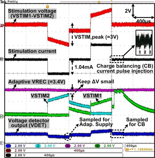
Fig. 15.
Measured waveforms of the current stimulator with RS = 2 kΩ and CDL = 500 nF connected in series between two active sites, as shown in Fig. 8, demonstrating the adaptive VREC control and active charge balancing operations through the voltage readout channel.

