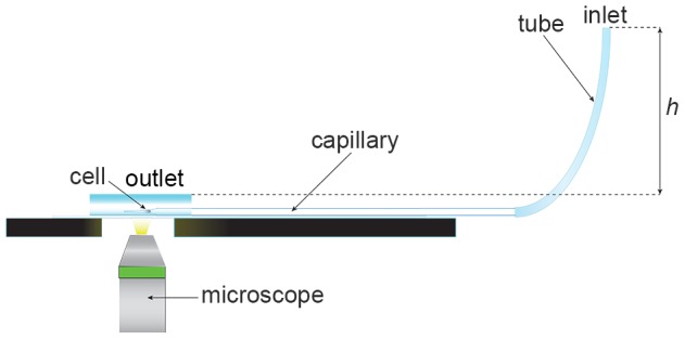
Figure 1. Capillary micromechanics setup.

Capillary micromechanics; schematic of experimental setup. In brief: The tip of a horizontally stabilized tapered capillary (3-μm-wide) leads into a liquid drop of buffer solution (PBS). A cell is lodged in the tapered part of the capillary. A flexible tube is attached at the backside of the capillary. The filling height h of PBS buffer in the tubing determines the pressure difference in the system (1 mm H2O is 10 Pa, changed in steps of 10 Pa) and thereby the externally applied stress acting on the cell. Cells are imaged in real-time (shape and volume) using an inverted microscope (40x objective) at each pressure step after a cell lodges in the capillary.
