
Figure 1. Geometry and working principle of the MRR ultrasonic detector.
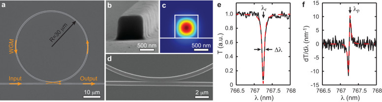
(a) Scanning electron micrograph of the MRR. (b) High-magnification view shows the square-shaped cross-section of the waveguide with a side length of 800 nm. (c) Calculated electric field distribution of the TM mode when the waveguide is immersed in water. (d) Close-up view of the gap between the ring and bus waveguides. (e) Transmission spectrum shows the dip caused by the strong WGM-induced optical resonance. Black line: experimental data; red dashed-line: fitted curve based on Lorenzian model. λr is 767.27 nm, Δλ is 73.8 pm, Q factor is λr/Δλ = 10400. (f) The normalized transmission change with respect to the resonance shift derived by the first derivative of the transmission spectrum. Black line: experimental data; red dashed-line: calculated curve from the fitted result in the panel (e). The probing wavelength λp indicated by arrow is set to the maximum sensitivity point of PA detection at 767.31 nm.