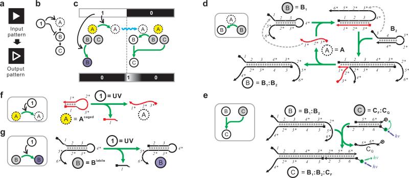
Figure 1.
High-level description and molecular detail of an incoherent feed-forward loop that performs edge detection. (a) Definition of edge detection with a binary input. (b) High-level description of the incoherent feed-forward loop. The input signal is denoted as “1”. The only fast-diffusing species (“A”) is denoted with a dashed circle. (c) Detailed mechanism of the incoherent feed-forward loop. The input signal can turn caged A (yellow) into active A (white) and simultaneously turn inactive B (gray) into ablated B (unable to be activated by A, purple). Activated A can then diffuse (blue squiggle) to the area where input signal is absent (= 0) and turn inactive B (gray) into active B (white). Active B can then combine with inactive C (gray) to form active C (white) near the 1/0 boundary. (d-e) Implementation of the circuit shown in (c) using a CHA circuit. Active A, inactive B, and active B are represented by A, B1, and the B1:B2 duplex, respectively. For simplicity B2 is not shown in (c). A can catalyze the formation of the B1:B2 duplex through the depicted pathway. Inactive C is represented by the CF:CQ duplex, where the fluorescence is quenched. Active C is represented by the B1:B2:CF complex, where the fluorescence is unquenched. Domains 1, 2, 3, 5, and 6 are 8-nt long; domain 4 is 11-nt long. See Supplementary Table S1 and Supplementary Figure S8a for sequences. (f) Mechanisms of the photo-activation of Acaged. (g) Mechanisms of the photo-ablation of B1labile. See Supplementary Figure S1a for chemical structure of the photo-cleavable linker.

