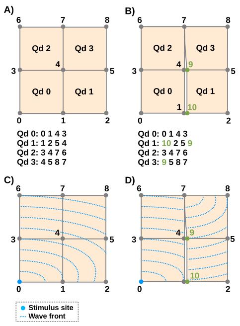
Fig. 1.
Upper panels show element connectivity of continuous FE (left) and dFE (right) mesh. Lower panels indicate wave front propagation patterns for both cases. In the right dFE panel nodes 1 and 4 are decoupled, preventing impulse propagation across the line 1-4-7, only node 7 allows transduction. Impact of nodal splitting upon propagation pattern when stimulating node 0 is illustrated using artificial isochrones.

