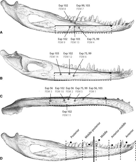
Figure 1.

Gage locations, reference axes and bite points. The mandible of the Alligator in lateral (A), medial (B) and ventral (C) views illustrating the locations of experimental strain gages (black text) and equivalent areas in the FEM (finite element model) (gray text). The reference axis used to standardize strain orientations across all experiments and the FEM is shown in all three views as a black arrow from the anterior point of the external mandibular fenestra to the posterior base of the 6th dentary tooth; strains rotated counterclockwise from this axis are positive, those rotated clockwise are negative. Dotted lines in A, B and C indicate the reference planes. Bite locations during in vivo experiments (dotted lines) and constraints in the FEM (black dots) are shown in (D). The solid black line in (D) indicates the section used to determine axis of bending in the FEM.
