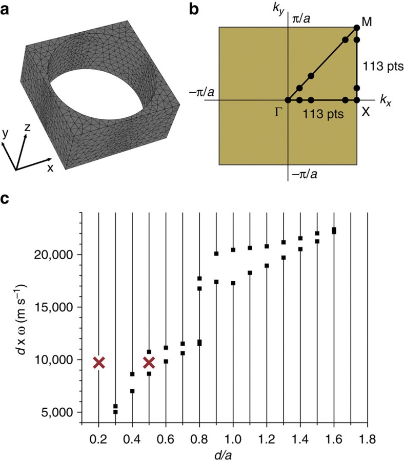
Figure 2. Band structure calculations using FEM.
(a) A representative unit cell used in the FEM calculations with hole-filling factor f=0.7. A typical mesh structure is also shown. (b) The first BZ of the square PnC lattice in k-space (orange), with the irreducible zone (where calculations are performed) inside the triangle with corners at points Γ, X and M. One typical set of evenly divided k-points is also indicated. Other, uneven divisions were used, as well. (c) The scaled width of the phononic band gap in SiN (empty region in angular frequency ω) as a function of the ratio of the thickness of the membrane d and the lattice constant a. The red crosses show the chosen design values.

