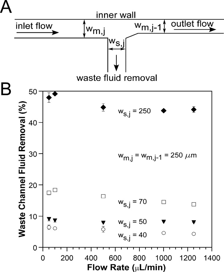
Figure 5.
(A) Schematic illustrating the dimensions of a device with a single waste channel located at the W2 position (Figure 3). (B) Percentage of fluid actually removed from devices designed for the removal of 5% (○), 10% (▼), 20% (◻), and 50% (♦) of the inlet fluid. The widths in μm are listed for each of the devices. The widths of the main channel before the waste channel, wm,j, and after the waste channel, wm,j−1, are both 250 μm.

