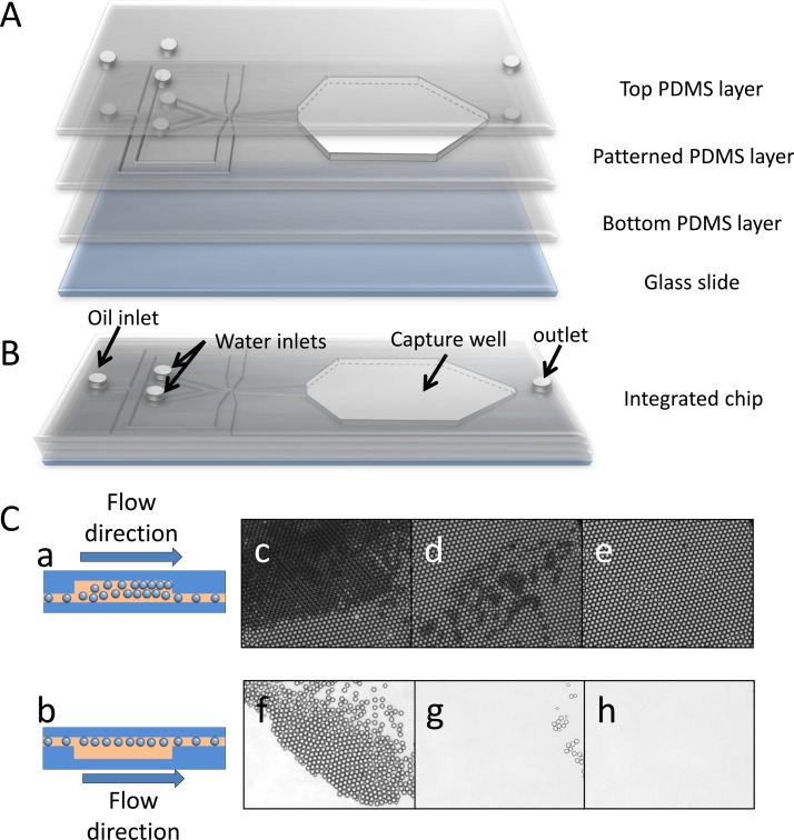
Figure 2.
(A) Three-dimensional illustration of a droplet capture chip, including a top PDMS layer, a patterned PDMS layer with capture well excised, a flat bottom PDMS layer and a glass slide. (B) Schematic diagram of integrated chip. (C) Schematic of capture well when capturing (a) and releasing (b) droplets. (c) Close-packed droplets layers are generated when droplets gather in the capture well. (d) Lower layers of droplets are swept away when the water phases are stopped with the oil flow rate set at 0.1 ml/h. (e) Mono-layer of close-packing droplets is generated after sweeping for several minutes. Release of droplets after flipping-over the microfluidic chip for 1 min (f), 2 min (g), and 4 min (h).

