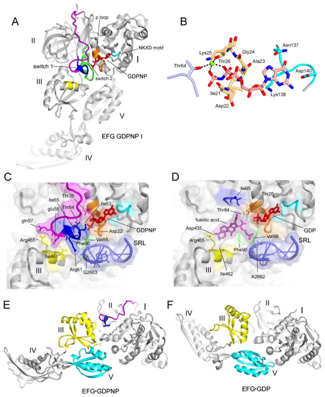
Fig. 6. Structuring of switch loop I.
(A) EF-G GDPNP-I showing the path of switch loop I (residues 40–67) which was disordered in all previous EF-G structures. The conserved core (residues 59–67) is shown in blue, and the rest of the switch loop I (residues 40–58) in magenta. (B) Structure of the GDPNP binding pocket, showing interactions with switch loop I (light blue), the guanosine recognition motif (cyan) and P loop (orange). A magnesium ion coordinating the β and γ phosphates of GDPNP is shown as a green sphere. (C) The switch I region in the GDPNP-I complex and (D) The fusidic acid binding site in the Fus complex, in the same view as for (C). In (C) and (D), showing the conserved core of switch loop I (blue) and the rest of switch loop I (magenta), guanosine recognition motif (cyan), phosphate binding loop (orange) and switch loop 2 (green) and domain III contacts (yellow); the components are shown with transparent molecular surface representations. (E) EF-G from the GDPNP-I structure containing a structured switch loop I (blue, magenta) compared with (F) the structure of free EFG·GDP containing a disordered switch loop I (27) showing movement of domains III (yellow), IV and V (cyan).

