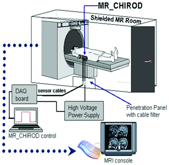
Figure 2.

The Magnetic Resonance Compatible Hand-Induced Robotic Device (MR_CHIROD) concept for online brain MRI. The current MR_CHIROD (version 2) is controlled by a data acquisition (DAQ) card and DAQ software on a PC located in the operator room, outside the RF-shielded MR system. This DAQ/PC configuration can be re-engineered into a compact electronic unit. The PC via its A/D and D/A boards collects, stores and visualizes in real-time the encoder and torque measurements. Based on the selected exercise protocol, it also sends the required control voltage to the MR_CHIROD actuators. The PC voltage output is amplified using a very fast, high-voltage power supply and a high-voltage, low-current amplifier circuit board provided by the ERF manufacturer. The damper consists of two electrodes and contains the ERF fluid. The piston (piston shaft drawn in Fig. 1) moves through the ERF fluid with a controlled force of contraction provided by the voltage-controlled variable viscosity of the ERF fluid. A Faraday cage encloses the core of the device, allowing a necessary opening for the movable piston shaft. The negative electrode of the damper (connecting to the negative terminal of the power supply) and the Faraday cage are grounded to the penetration panel of the MR room. A low-pass filter (LPF) is attached to the penetration panel. Sensor readings (force, position) are transmitted through the penetration panel via grounded DSub-9 connectors. The sensor wires are coaxially shielded and grounded to the penetration panel. The sensor readings are used for real-time, closed-loop control of the ERF resistive element. The output from the control loop regulates the voltage output of the power supply, in turn ensuring control of the ERF resistive element and force of contraction.
