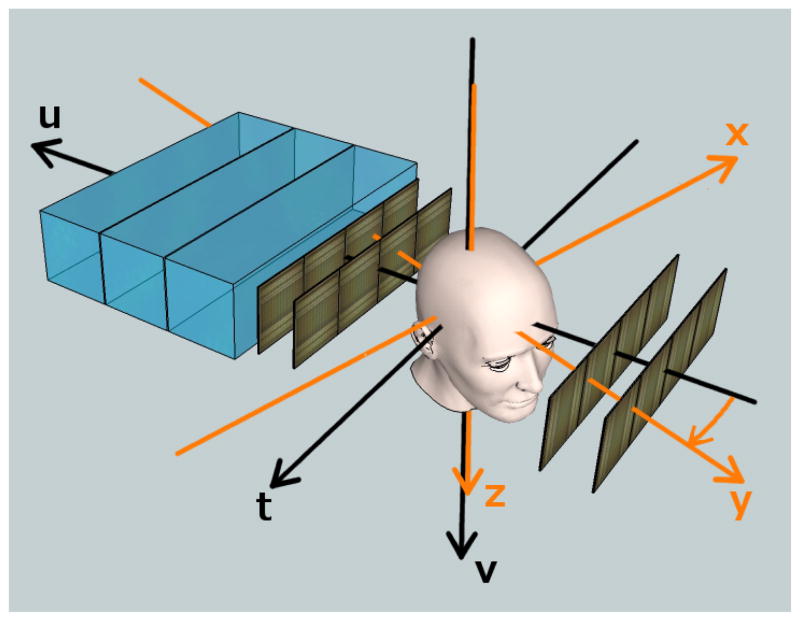
Fig. 2.
Two coordinates systems are used in a proton CT scanner, here illustrated in a sketch of the second-generation proton CT scanner. The proton cone beam enters from the right and its central axis is parallel to the u-axis. The phantom can be rotated about the v-axis, but for the radiography experiment, it was kept at 0 degrees (y-axis anti-parallel to the u-axis).

