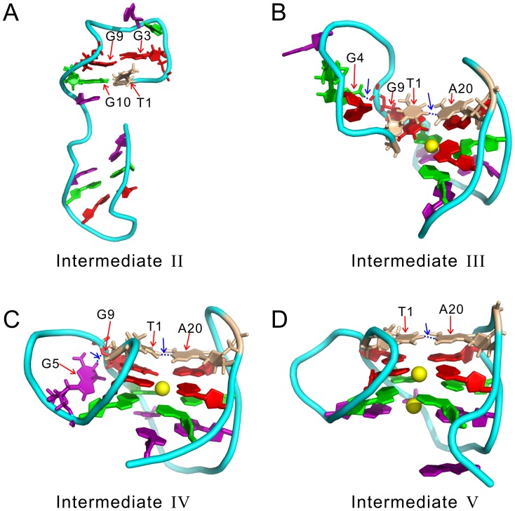
Figure 3. The detailed tertiary structures of the intermediates.
(A)–(D) are for the intermediate-II, III, IV, and V, respectively. The structures are taken from the largest cluster in the corresponding conventional MD trajectories. They are slightly different from that shown in Figure 1, which are obtained from BEMD simulations. The non-native hydrogen bonds are plotted as blue dashed lines and pointed by blue arrows. The  ions bound to DNA are shown as yellow spheres.

