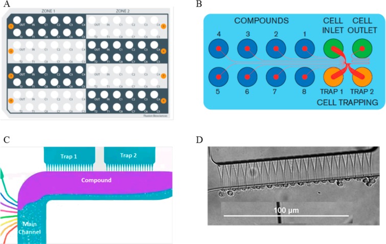
Figure 1.
(A) The IonFlux 16 consists of a 96-well plate with eight patterns (colored in gray and black and numbered in orange circles). (B) Each pattern has two trap wells (trap 1, trap 2) that are filled with ICS. Cells are loaded in the “INLET” wells, and waste is collected in the “OUTLET” well. Compounds are loaded in wells C1–C8. (C) A zoomed in view of the trap zones. The cells are suspended in ECS flow in the “main channel”, which flows past the trap zones. When a compound is released, the laminar flow ensures that the compound and ECS streams do not mix. (D) Image showing cells trapped in a trap zone. (Parts A–C were developed by Fluxion Biosciences.)

