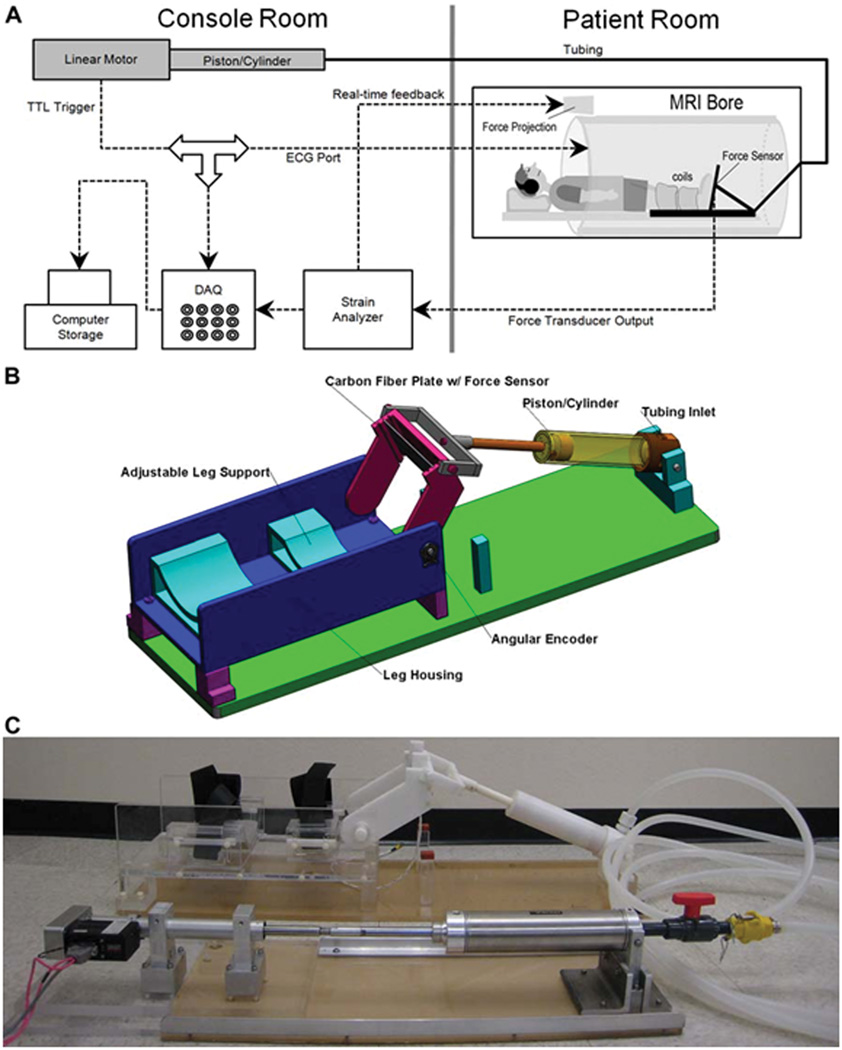
Fig. 1.
(A) Schematic diagram of the experimental setup. The experimental components are interconnected via coaxial cables. Work output of the motor was transmitted to the foot pedal via hydraulic fluid (water) in high-pressure tubing. The tube passed from the console room to the MRI scanning room through a waveguide in the wall. Force data from the foot pedal was projected onto the white front surface of the magnet through a projector for real-time feedback to the subject. An electronic trigger signal was transmitted directly from the motor to the ECG port of the scanner at a preselected point of each contraction cycle for gated image acquisition. (B) Schematic of the foot pedal apparatus – Assembly of all CAD parts. Different components are annotated. (C) Photo of the actual Foot-Pedal Device. The motor is shown in the lower left connected to the stainless steel piston-cylinder, hydraulic tubing coiled on the right, connected to the white, non-metallic piston-cylinder which goes inside the magnet bore. The piston can be seen connected to the foot-pedal in the upper middle part of the picture.

