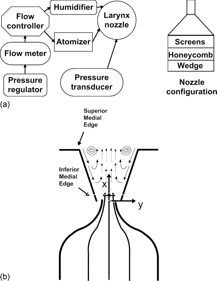
Figure 1.
Experimental setup: (a) Flow control schematics. (b) Schematic of the PIV measurement at the mid-membranous plane (i.e., coronal plane). The z axis is pointing out of the page. u, v, and w are velocity components in the x, y, and z directions. The PIV camera is located on the x-z plane, anterior and superior to the larynx. The laser sheet is projected from above the larynx in the x-y plane.

