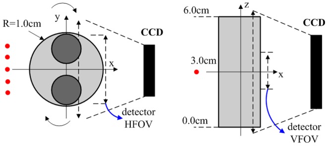
Figure 3. Simulation experiment sketch.

A full-angle CCD camera–based imaging system configuration was used for the data simulation. The imaged object was a cylinder phantom with two embedded cylinder heterogeneities (different absorption coefficients). For each projection, five different excitation sources were scanned (red dots), and the detectors, which corresponded to selected detection points on the image plane, were within 1.8 cm of the detector horizontal FOV (HFOV) and 2.2 cm of the detector vertical FOV (VFOV) with a detector spacing of 0.2 cm.
