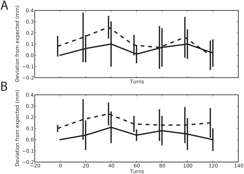
Figure 1. Measurements of electrode advance. advancement and retraction for printed and machined microdrive.
A 250 um glass electrode was loaded into the center position of the electrode grid. The drive was placed in rig that allowed us to measure the electrode travel as we turned the advancer. The electrode was advanced and retracted five times. Travel measurements were taken every 20 turns. Solid line shows data from the advancing phase and the dotted line shows data from the retracting phase for the printed (A) and machined version (B) of the microdrive. At the start of each cycle we realigned the electrode position to zero.

