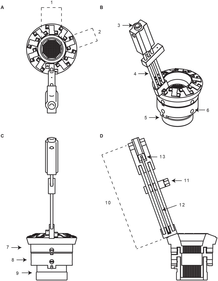
Figure 4. Schematic of complete PriED assembly, showing stacked base on chamber with one tower attached.
(A) Top-down view of micro-drive highlighting the grid (1) and pad (2) where each tower attaches to the base. (B) Isometric view of the micro-drive. The sleeve (3), rails (4), notch that aligns with the grid (5), and set screw that attaches to the chamber (6). (C) Side-view highlighting the upper (7) and lower (8) base of the micro-drive when attached to the chamber (9). (D) Cut-away view showing tower (10), shuttle (11), lead screw (12), and upper adaptor (13).

