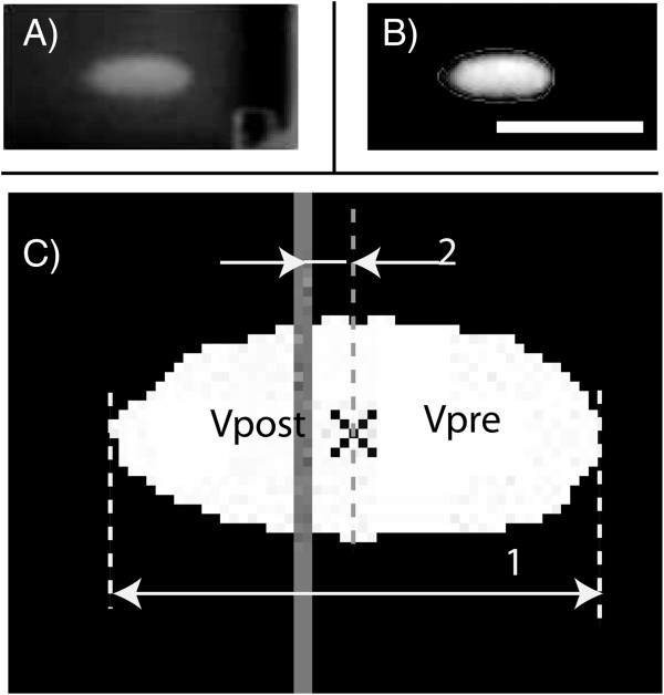
Figure 3.
An example of the image processing procedure (A, B, C).1 represents the lesion length and 2 represents the shift of lesion center with respect to focal plane (solid gray line). The lesion was divided into two parts by its middle point, and the volume of each part was calculated (VPre and VPost). The ultrasound source was located to the right of the image. The scale bar represents 5 mm.

