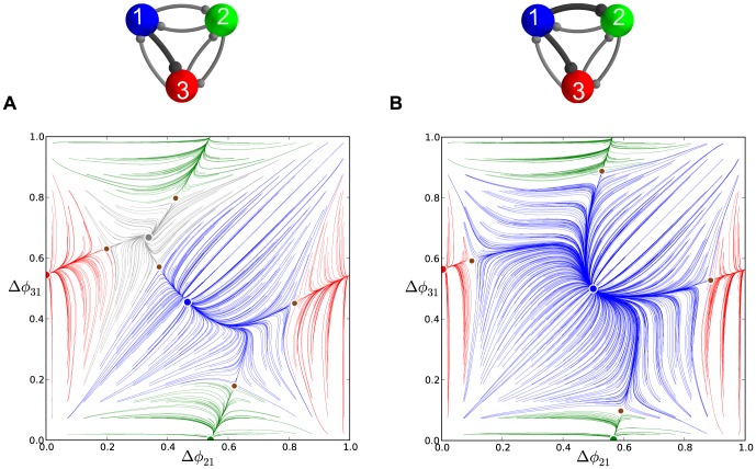
Figure 17. Representative phase lag maps for motifs with other connection asymmetry types, Part 1.
(A) Counter-clockwise biased motif with the single strengthened connection  and medium duty cycle. The phase lag map lacks the FP at
  and the saddle near the dominating blue FP at
  . (B) Motif with a strongly inhibiting cell 1 due to two strengthened connections:
  . The phase lag map with the strongly dominating FP at
  for the
  rhythm whose attractor basin expands over those of the FPs corresponding to clockwise
  and counter-clockwise
  traveling waves. This larger basin has narrowed those of the coexisting stable green FP at
  for the
  rhythm and the red FP at
  for the
  rhythm.

