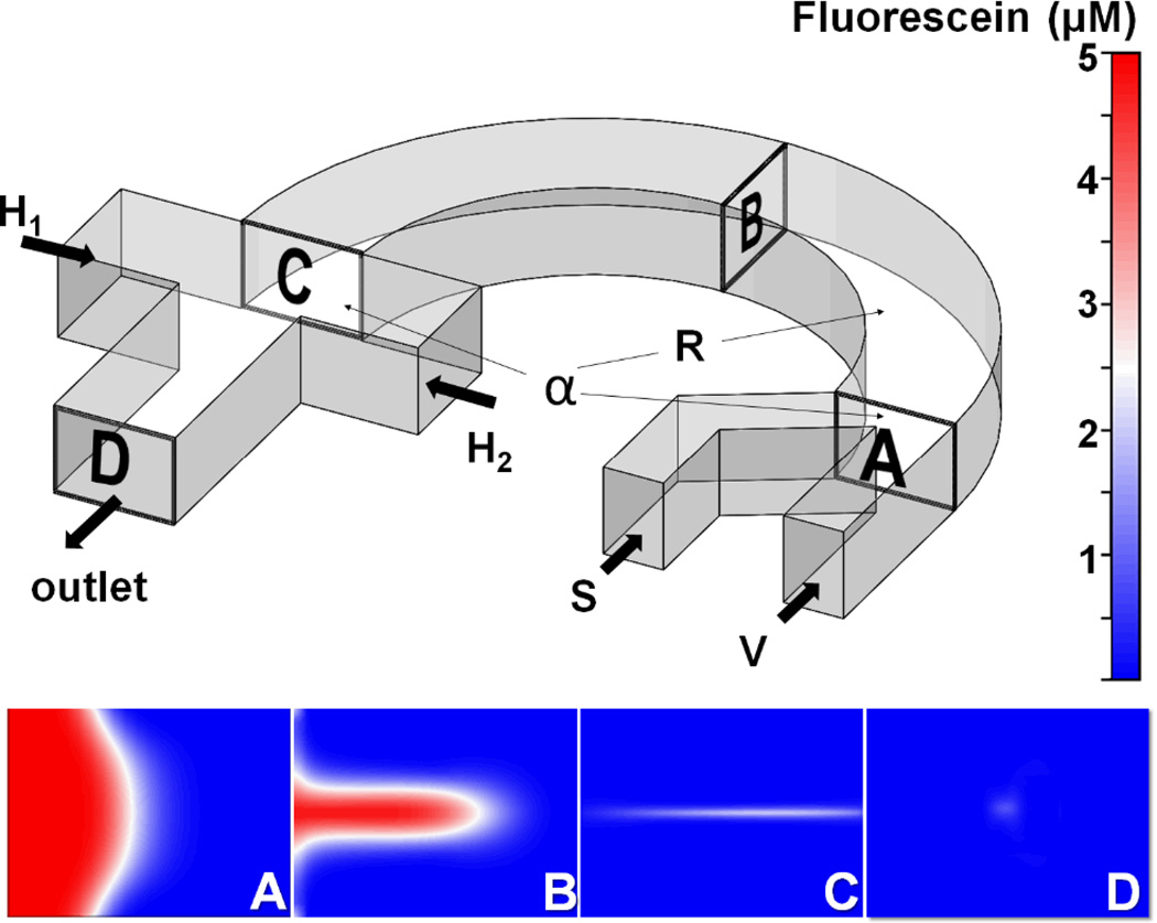
Fig. 1.
Schematic diagram of the “microfluidic drifting” 3D hydrodynamic focusing device. The sample flow (S) and vertical-focusing sheath flow (V) are input from the right end of the curved channel and exit from the left end. The insets (A, B, C, and D) are locations of CFD simulation of the sample flow distribution on the cross sections of the curved channel. The co-flow interface transfers from vertical distribution at the input end (inset A) to the Gaussian distribution at the middle of the channel (inset B), and finally to the sandwiched distribution (inset C). Then two horizontal-focusing sheath flows (H1 and H2) are added in order to pinch the sample flow into a confined area in the center of the channel (inset D).

