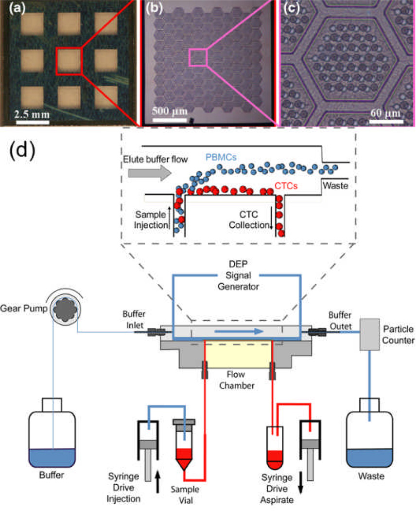
Figure 3.
(a-c) Images of a 3-D microfilter, used for size-based mechanical separation of CTCs, at different magnifications. (d) Schematic of a dielectrophoretic CTC separation device, with detail provided for the flow chamber where an electrode sheet along the chamber floor generates an AC voltage to spatially separate CTCs from PBMCs via a DEP force. Reproduced from Refs. 23, 27 with permission from AIP and Springer.

