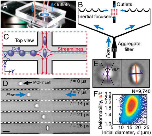
Fig. 2.

Principles of “hydrodynamic stretching” based deformability cytometry. (A) A photograph of the microfluidic deformability cytometry device. (B) A schematic of the microfluidic device including the “inertial focusing” region and the “hydrodynamic stretching” region. (C) A schematic of the deformation of a cell delivered to the center of an extensional flow via inertial focusing. (D) High-speed microscopic images showing a focused cell entering the extensional flow region. (E) Definition of the shape parameters extracted from images. (F) Density scatter plot of size and deformability measurements. Images reproduced from ref. 9.
