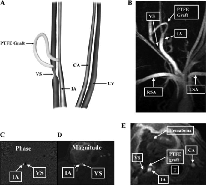
Fig. 1.
Placement of the polytetrafluoroethylene (PTFE) hemodialysis graft and representative MRI and phase-contrast magnetic resonance angiography (PC MRA) of the vein-to-graft anastomosis. A: placement of the PTFE hemodialysis graft. CA, control carotid artery; CV, control jugular vein; VS, venous stenosis, IA, inflow artery. B: MRI with PC MRA performed on day 14 that shows high grade VS formation. RSA, right subclavian artery; LSA, left subclavian artery. C: PC MRA showing the direction of blood vessels in the opposite direction as depicted by black in the VS and white in the IA. D: magnitude of the blood flow in the same vessels. E: a hematoma surrounding the PTFE graft. T, trachea.

