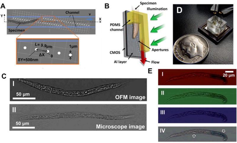
Fig. 2.

Images pertaining to the Optofluidic Microscope (OFM). (A) Configuration of the CMOS sensor, with its two parallel lines of apertures, oriented at a small angle Ɵ to the microfluidic channel through which the sample moves. (B) A three-dimensional representation of a nematode specimen moving through the imaging channel. (C) Comparison of images obtained by the OFM and a conventional microscope; image is of a nematode. (D) OFM device, with electrodes at either end of the imaging channel to create an electric field to suppress rotation of circular/elliptical samples. Image reproduced from the authors’ website. (E) Image captures of a nematode sample by red, green, and blue pixels of an RGB CMOS sensor in the color-capable OFM; the composite image is also shown, with the two dye-stained regions of the nematode highlighted with arrows. Images reproduced from ref. 26, 30.
