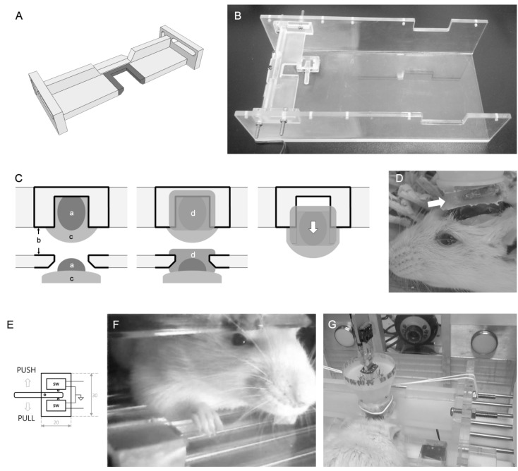
Fig. 1.
Head restraining apparatus. (A) Drawing of the head-restraining bar. Shaded area indicates the rim of the port. (B) Practical implementation of the head-restraining bar and the push-pull lever. (C) The mounter is implementated during surgery by applying additional dental cement between the bar and rat skull. a: dental cement applied for electrode implantation, b: Parafilm (surrounded by black solid-lines), c: rat skull, d: mounter. After the mounter is harden, it can be pulled off (white arrow) since Parafile separates the restraining bar and mounter. (D) Head restraining is simply achieved by the guide rails in the mounter (white arrow). (E) The drawing of the push-pull lever. (F) An example of a rat performing ICSS tasks. The push-pull lever is ergonomically designed for head-restrained rats. (G) The molded overhead mounter is inserted into the port, at the middle of the fixation bar and simply tightened by a rubber band.

