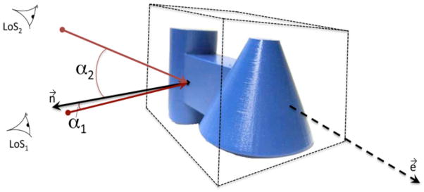
Figure 1.

A graphical depiction of the determination of planar views and ¾ views of objects. Each image frame was coded as planar, ¾ or otherwise by calculating the angle between the Line of Sight (LoS) and the normal vectors of the front, top, and side face of the object’s bounding box. The bounding box was oriented so it had one side parallel to the object’s main axis of elongation (e⃗) and its faces were parallel to the object’s sides. The figure shows an example of the calculation, for one side of the bounding box and for two orientations: LoS1 corresponds to a planar view and LoS2 corresponds to a ¾ view; n⃗ is the vector normal to the bounding box’s side.
