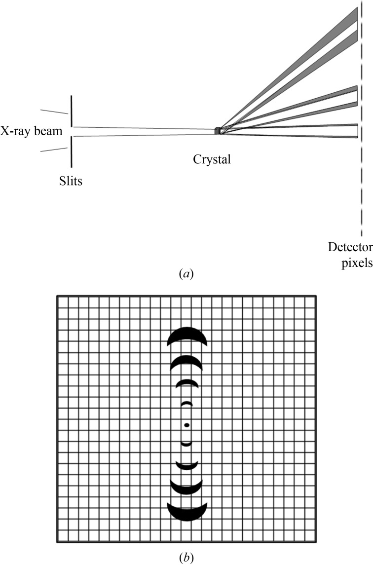
Figure 2.
Diagrams showing the effects of sample, beamline and detector parameters on the sharpness of recorded diffraction spots. (a) Matching the beam divergence and detector pixels in the presence of lattice variations δa/a and finite crystal/domain size s. The convergence of the incident X-ray beam is reduced using slits at a distance from the focus. The divergent beam after the crystal is broadened somewhat due to the finite size s of the crystal. The broadening of the lower angle reflection is increased further due to the variation in cell dimensions. However, it is reasonably well matched to the detector pixel size when the detector is set at the distance shown. The higher-order reflection at a greater angle is broadened further due to the lattice variation and now occupies several pixels. (b) Matching of diffraction spots to the detector resolution in the presence of misorientation of the domains and a variation in the lattice parameter. The first-order reflection occupies one pixel in the azimuthal direction and, by the definition in this paper, is matched to the pixel size when the detector is set at this distance. However, it is not matched in the radial direction. The fourth-order reflection occupies approximately four pixels in the azimuthal direction and one pixel in the radial direction.

