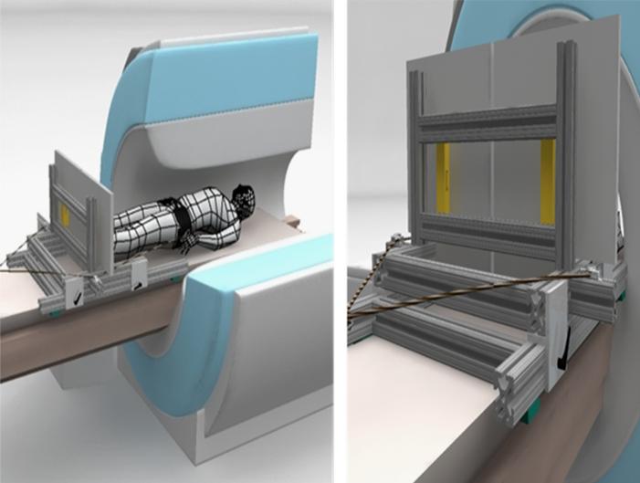
Fig. 1.
Schematic of MR-compatible posture platform. Left figure shows cut-away view of MR scanner with subject lying supine with feet against independently instrumented platforms. An axial compressive force between the subject and plate is applied via a belt around subject's waist. In view on right, axial load cells (shown in gold) can be seen between platforms and vertical supports.

