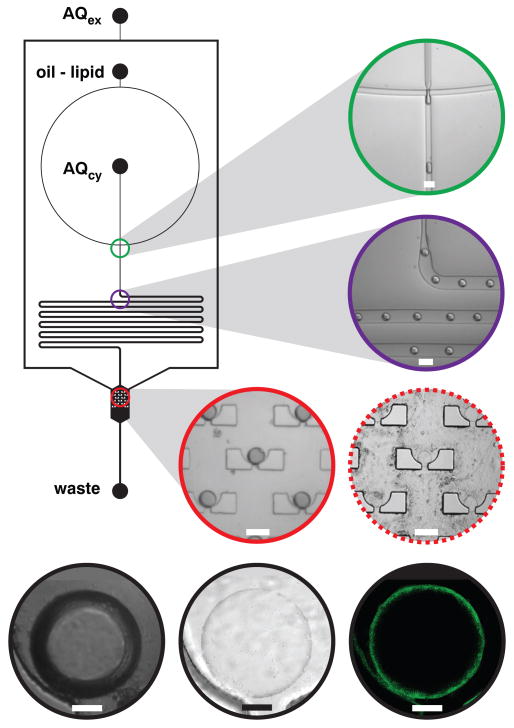
Figure 2. Vesicle assembly circuit schematic and imaging.
Three fluidic inputs deliver extracellular aqueous medium (AQex,TAE buffer), oil-lipid mixture (DOPC in squalene, CMC = 2 mM), and cytoplasmic aqueous medium (AQcy,TAE buffer) to the circuit and one output removes fluids to waste. The capture array chamber is 1.2 mm wide. Each 120-μm-diameter cup contains a 30-μm-wide drain. All other channels are 120 μm wide. Channel depth is 50 μm. DOPC-stabilized water-in-oil droplets emerge from the flow-focusing junction (green, scale = 100 μm), travel through a delay line (violet, scale = 100 μm) and arrive at the droplet capture chamber (red, scale = 100 μm) where an array of cups captures single droplets. Driving a phase boundary over the trapped droplets deposits an external monolayer of lipids, transforming the water-in-oil droplets into vesicles (dashed red, scale = 100 μm). High-resolution DIC imaging of a trapped droplet displays strong DIC between the internal aqueous and external oil phase (black left, scale = 20 μm), but after a single monolayer deposition, the refractive indices of the external and internal aqueous phase contrast weakly (black center, scale = 20 μm). High-resolution confocal fluorescence imaging of the same vesicle labeled with fluorescent lipid 2 yielded clean annular sections (black right, scale = 20 μm).

