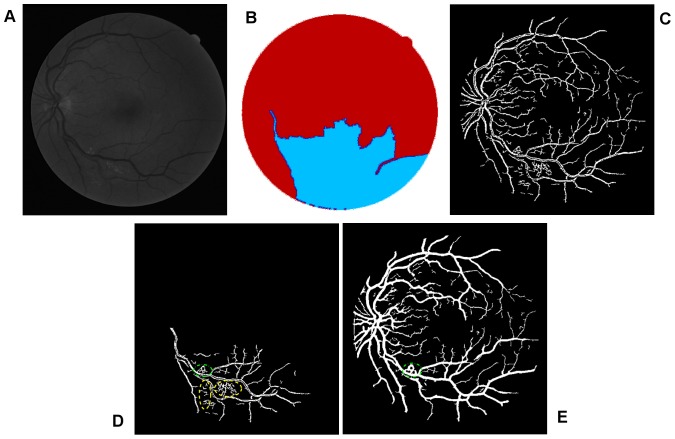
Figure 11. An example showing noise effects from a pathological image.
(A) The green channel of original image named 03_test. (B) Colour coded mapping. (C) The extracted enhanced image after a global threshold and a global connectivity constraint. (D) The part in relation to blue coded mapping with pathological regions indicated by yellow dash and green dash-dot lines. (E) Final segmentation with part of pathological tissue existing indicated by green dash-dot line.

