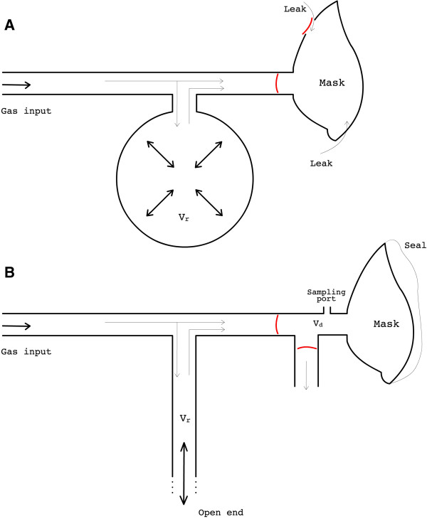
Figure 1.
Schematic comparison between the new breathing circuit and a non-rebreathing oxygen mask. A typical oxygen mask/circuit is shown on the top (A). The input gas may go straight to the mask or fill the breathing bag when delivery rate exceeds uptake rate (e.g. during the expiratory phase of the breathing cycle). Whenever uptake exceeds delivery rate the bag empties to provide supplementary gas for inspiration. Expired gases leave the mask through vents controlled by valves. Gases inside the mask are often contaminated by air that leak in through the edges of the mask and/or through the vents when valves are malfunctioning. This compromises control over the inspiratory gases as well as the accurate monitoring of end-tidal values. To avoid the latter concerns the new breathing circuit we have developed (B) uses a non-vented mask providing a sealed fit to the subject’s face. But also, the breathing bag is replaced by a long limb reservoir with an open end, which makes the circuit completely safe as the person can normally breathe room air if no gas is supplied. Besides, the geometry of such reservoir permits faster transitions in FiO2 and FiCO2. Expired gases are exhausted through a second limb, controlled by an efficient unidirectional valve. Lastly, a sampling port is installed adjoined to the mask to help the respiratory monitoring. Vr = volume of the reservoir; Vd = dead space added by appending the dual limb system to the mask.

