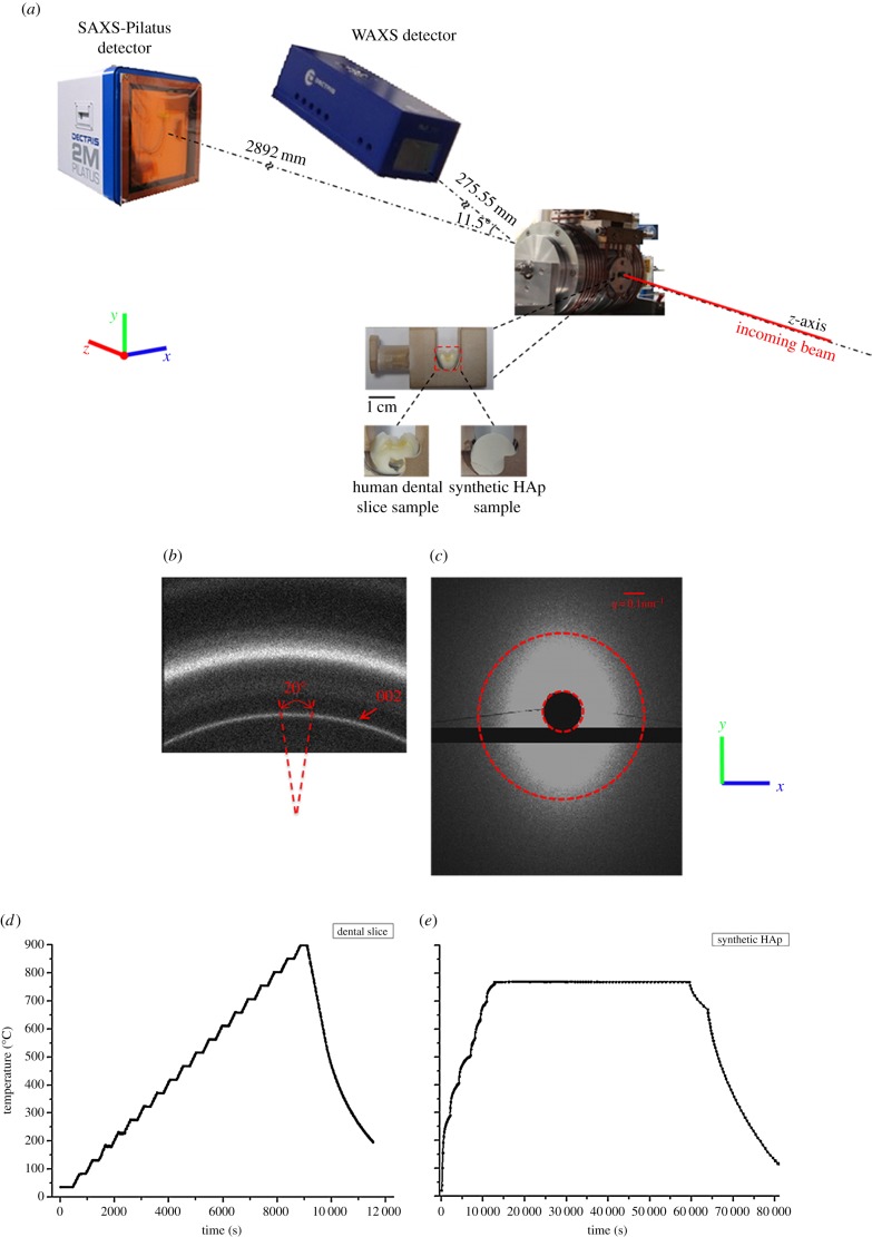
Figure 1.
(a) Schematic of the in situ SAXS/WAXS experimental set-up that ensured that the WAXS and SAXS patterns were collected simultaneously. (b) A representative WAXS pattern showing the Debye–Sherrer ring corresponding to the (002) peak indicated by the red arrow. On the ring, the section along the y-axis in (a) was ‘caked’ (see text) with a 20° range in order to capture the peak shift upon heating and cooling process. (c) A representative SAXS pattern. The dark region in the middle is the beamstop. The ellipsoidal shape of the pattern indicates a partial alignment of HAp crystallites. The pattern for randomly distributed crystals is a round disc with the outline marked with red dashed circle. (d,e) Illustration of the different heating and cooling protocols used for the human dental slice samples and the synthetic HAp powders sample. (Online version in colour.)

