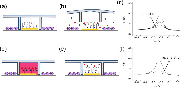
Figure 2.
Working principle of the microfluidic device. (a) Cells are seeded inside the PDMS cups. (b) PDMS cups are lifted for detection. (c) A schematic of SWV signals during detection. Redox current goes down as more secreted molecules bind to the electrode. (d) To regenerate a sensor after a predertimned time of signal collection, PDMS cups are pressed down to protect the cells and regeneration buffer is introduced. (e) The aptasensor is ready for another round of measurement. (f) The redox activity of the electrode is recovered after regeneration process with SWV signal returning to original, pre-detection level.

