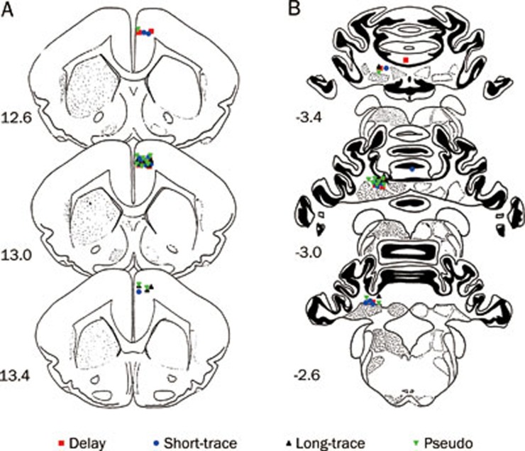
Figure 2.
Histological reconstructions of the electrode and infusion cannula tips. Schematic illustration of the locations of all electrode tips (A) and all infusion cannula tips (B) for the delay (▪ n=9), short-trace (• n=10), long-trace (▴ n=8), and pseudo conditioned (▾ n=10) groups, respectively. Note that one infusion cannula tip of the delay conditioned group and one infusion cannula tip of the short-trace conditioned group were not in or near the left cerebellar interpositus nucleus. Numbers to the left represent distance (mm) from the frontal zero plane. The coronal brain plates are adapted from the atlas of Rapisarda and Bacchelli (1977).

