Fig. 3.

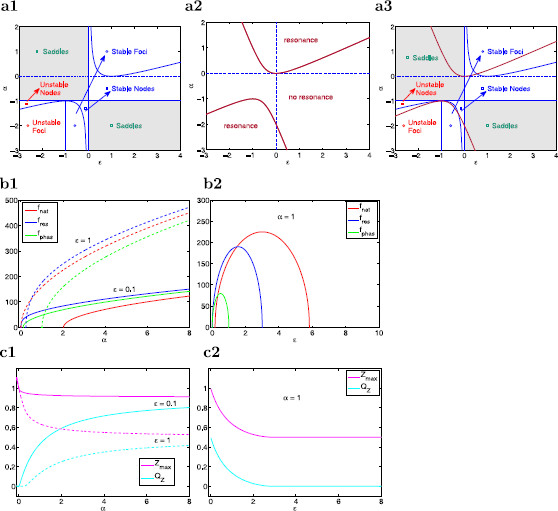
Stability and resonant properties for the reduced two-dimensional linear system (14)–(15). a Stability and resonance diagrams in the α–ϵ parameter space. a1 Stability diagram for the autonomous system. The blue curves separate between regions with different stability properties. a2 Resonance diagram. The red curves separate between regions where the system does (above and below) and does not (middle) exhibit resonance. a3 Superimposed stability (blue curves) and resonance (red curves) diagrams showing that intrinsic oscillations and resonance may occur in the absence of the other. b Natural (), resonant (), and phase-resonant () frequencies as a function of α (b1) and ϵ (b2) illustrating that these characteristic frequencies have different values (b1 and b2) and different monotonic properties (b2) as the model parameters change. c Maximum impedance () and resonance amplitude () as a function of α (c1) and ϵ (c2) illustrating the two basic mechanisms of generation of resonance in 2D linear systems. c1 As α increases, resonance results from a decrease in both and with decreasing faster than . c2 As ϵ decreases (time-scale separation increases), resonance results from an increase in with fixed
