
Figure 2.
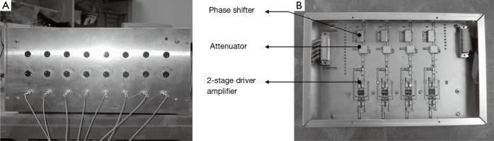
The front panel of the controller module (A) shows 2 banks of 8 dials each. The upper bank of potentiometer dials is for amplitude control and the lower bank of potentiometer dials is for phase control. The controller module consists of 2 boards of 4 channels each. Each channel (B) consists of a voltage controlled phase shifter, a gain stage and a driver for the current source end stage.