
Figure 3.
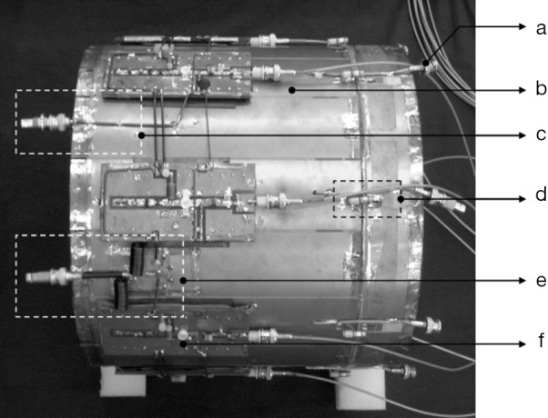
Top view of the completed transmit coil with the rung integrated current sources mounted on it. (a) is the output of the built-in magnetic field probe; (b) is the RF shield; (c) is gate voltage input connector; (d) is the trimmer capacitor connecting the rung to the RF shield; (e) is the drain voltage input connector and (f) is the MOSFET voltage controlled current source board. RF, radio frequency; MOSFET, metal-oxide-semiconductor field effect transistor.