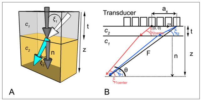
Figure 1.

(A) Snell’s law is depicted in three dimensions at the interface between medium 1 (top), having propagation velocity c1, and medium 2 (bottom), having propagation velocity c2. The white arrow indicates the direction of a wavefront incident on the interface at angle ξ1 with respect to the normal (dark gray arrow). Upon entering the second medium, the wavefront travels at an angle ξ2 with respect to the normal. (B) Propagation paths for the proposed two layer model (shown in two dimensions only). Steering vector F is depicted for an outer element (black arrow); red and blue arrows indicate the actual propagation paths used to compute corrected delays for center and outer elements, respectively. F is the steering vector, n is the normal to the bone–tissue interface, ax is the element coordinate in the x direction, c1 and c2 are the propagation velocities in tissue and bone, respectively, z is the focal distance, and t is the thickness of the planar layer (skull or Lucite plate).
