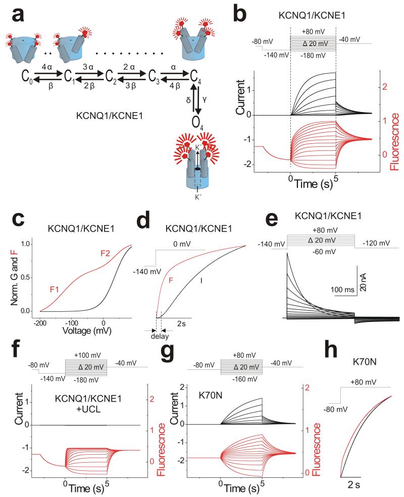
Figure 7. Model for KCNQ1/KCNE1 channel gating.
(a) A 6-state allosteric gating scheme for KCNQ1/KCNE1 channels. Horizontal transitions represent independent S4 movements that increase the fluorescence to an intermediate level. The vertical transition represents concerted channel opening with a concomitant additional fluorescence increase. Cartoon shows KCNQ1 channel labeled with a fluorophore on S3-S4 with all four voltage sensors in the resting state (C0), with one (C1), or four (C4) voltage sensor activated without channel opening (top) that is followed by a concerted conformational change of all four S4s associated with channel opening (O4) (bottom).
(b) Model simulation of current (black) and fluorescence (red) for KCNQ1/KCNE1 channel using the indicated voltage protocol (top). Note that all parameters in the model are determined by the estimates of the different rate constants and their voltage dependences from Figure 6 (Supplementary Table 1). Current and fluorescence traces were simulated using Berkeley Madonna (Berkeley, CA).
(c) Simulated G(V) and F(V) curves for KCNQ1/KCNE1 channels from simulation in b.
(d) Model simulation for activation time course of current (black) and fluorescence (red) at 0 mV (from b) in KCNQ1/KCNE1 channels.
(e) Model simulation of gating currents in KCNQ1/KCNE1 channels using the indicated voltage protocol (top) and same parameters as in b.
(f) Model simulation of current (black) and fluorescence (red) for KCNQ1/KCNE1 channel in the presence of UCL 2077 using the indicated voltage protocol (top). Same parameters as in (b), except that γ = 0 to prevent channel opening.
(g) Model simulation of current (black) and fluorescence (red) from KCNQ1/KCNE1 K70N channels using the indicated voltage protocol (top). Same parameters as in b, except that β and δ are slowed down compared to wild type to shift F1 by −40 mV and F2 by +20 mV as in Figure 5b.
(h) Model simulation for activation time course of current (black) and fluorescence (red) at +80 mV (from g) in KCNQ1/KCNE1 K70N channels.

