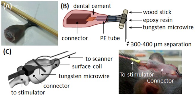
Figure 1. Details of the electrode set used in the current study.

(A) Photograph of the electrode set used in the current study. (B) Schematic diagram with details of the structure inside the electrode set. Two tungsten wires were welded to the copper tip of the connector, and extended approximately 5 mm through the PE tube. The connector and PE tube were fixed together with dental cement, and the extended tungsten wires were bent 90o around the wood stick and fixed using epoxy resin. The final length of the electrode wires, extended from the wood stick, was approximately 7 mm, and the distance between the 2 electrodes wires was approximately 300–400 µm. (C) The electrode was bent 90° to allow the placement of the MRI surface receiver coil over the rat head.
