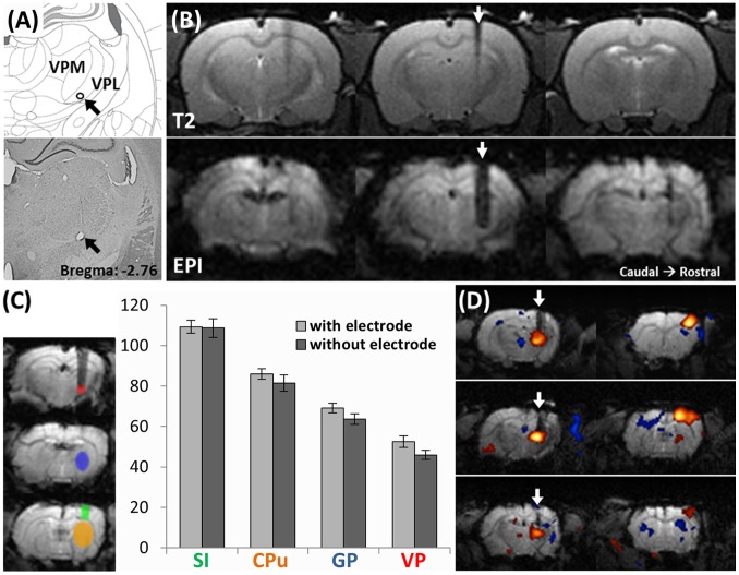
Figure 3. Evaluation of image distortion caused by tungsten electrode.
(A) An example of the identification of the electrode target site by cresyl violet stained brain section. The lesion at the electrode tip (black arrow) was produced by a constant electric current of 30 µA for 30 s before euthanizing the animal. The electrode lesion was located within the forepaw region of the VPL thalamus. (B) The tungsten electrode caused limited distortion to the MR signal around the electrode in T2 anatomical images (upper panel) and in EPI images (lower panel). In each panel, 3 serial scans from caudal (left) to rostral (right) are shown. The white arrows indicate the electrode track. (C) SNR in different brain areas in control rats and rats implanted with a tungsten electrode. The ROIs were defined as shown in the left panel: VP thalamus = red, globus pallidus (GP) = blue, caudate putamen (CPu) = yellow and S1 = green. In all 4 brain areas, no significant difference between the tungsten electrode compared with the control was observed. (D) Representative DBS-fMRI results from 3 individuals. White arrows indicate the electrode tracks. Positive BOLD response can be clearly observed in the VP thalamus and ipsilateral S1.

