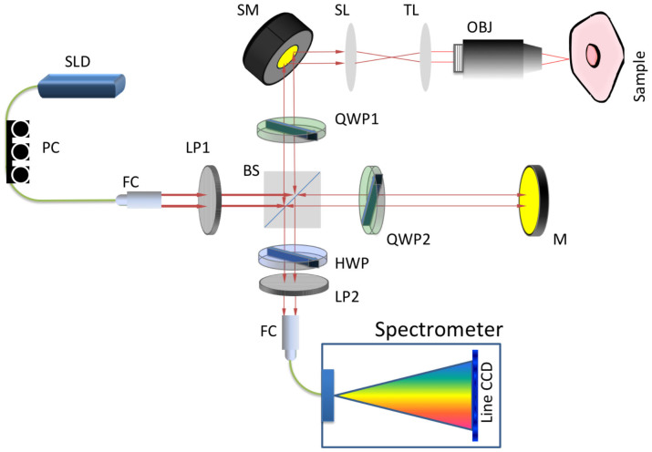
Figure 1. Schematic of CP-OCM Setup.
Red lines represent free space optical paths and green lines represent fiber guided optical paths. SLD: Super-luminescence laser diode; FC: fiber coupler/collimator. LP: linear polarizer; BS: beam splitter; QWP: quarter-wave plate; M: mirror; SM: scanning mirror; SL: scanning lens; TL: tube lens; OBJ: objective; HWP: half-wave plate.

