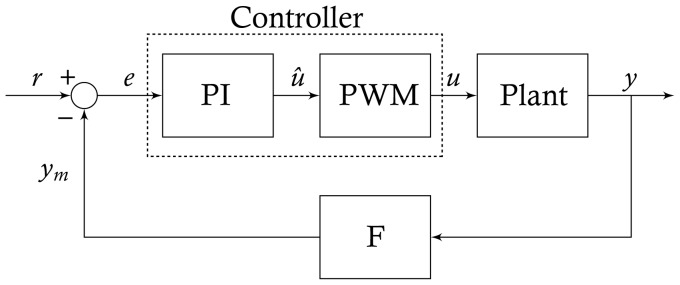
Figure 1. Feedback control block scheme.

The controller consists of a Proportional-Integral (PI) block followed by a Pulse Width Modulation (PWM) block encoding of the control input  . The PWM transforms the continuous control action
  into a train of rectangular pulses
  , which represents either Galactose (high) or Glucose (low). The alternating series of glucose and galactose pulses is applied to the cell population to be controlled (
 ), whose output
  (the controlled variable) is filtered (
 ) by a low-pass filter (
 ) before being fed back to the controller. The difference between
  and its desired reference level
  , namely the error
  , is used by the PI controller to compute the control input to be supplied to the system to minimize the error signal
  .
.
