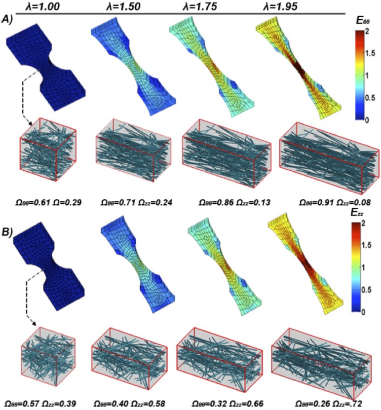
Fig. 6.
(a) Model circumferential Green strain Eθθ along the axis of pull plotted over the deformed model mesh at given sample stretches (λ). A representative neck region RVE network is shown and its corresponding fiber orientation tensor. (b) Model axial Green strain Ezz along the axis of pull plotted over the deformed model mesh at a given sample stretch (λ). A representative neck region RVE network is shown and its corresponding fiber orientation tensor.

